If you are citizen of an European Union member nation, you may not use this service unless you are at least 16 years old.
You already know Dokkio is an AI-powered assistant to organize & manage your digital files & messages. Very soon, Dokkio will support Outlook as well as One Drive. Check it out today!
This is a real short clip of my quadcopter hovering up and down and moving sideways. I tried to keep the height as minimal as possible as I am inside my living room, but as you can see, even with that it flies up to my head (approx 6 feet). Outside, it flies like a rocket! Unfortunately, my landing gear isn't as strong, and because I am not an experienced pilot, landing often causes parts to break off (especially the propellers). Regardless, while in the air, it flies wonderfully, and it truly is something else to see something you built actually fly!
Documentation Objective
My goal for this documentation is to teach someone who has absolutely no experience other than EE47 on how to build a quadcopter! Through this entire process, I have read/watched more than a hundred guides, forum threads, posts, and youtube videos about building a quadcopter. One thing I noticed was that even in the "newbie" friendly guides, there were still certain aspects that were not explained. With this guide, as long as you can solder, you should be able to recreate my project!
Why a Quadcopter?
I think first and foremost, the reason why I wanted to build a quadcopter was because it was so cool! I was genuinely excited to build it, and put a lot of passion and hardwork into this project. Along with that, drones (like quadcopters) provide interesting functionality that has many potential uses. Granted, as of now, commercial use is illegal, but the capabilities it provides are outstanding. One common use is for video and photography! For example, let's say I want to take an aerial video of New York City. Or maybe, I simply want to take a video of my roof and see if my long-lost and beloved frisbee is stuck up there without having to climb all the way. A drone like this can assume that role easily, and is already being used for purposes like this!
And even if, for some, it doesn't have a productive and practical use, people have come together to form a community of hobby drone fliers. It truly is amazing to make something fly and control it with just a wireless controller.
But that still doesn't answer the question: "why a quadcopter?" Well first, let's look into the common options you have for drones of a similar nature. You have:
Helicopter
Tricopter
Quadcopter
Hexacopter
Octocopter
The difference is clear straight from the name. I am sure we've all seen helicopters flying around. These are actually the most stable and maneuverable of aircrafts. This however, comes at a price, literally and figuratively. Helicopters are not only extremely costly from a monetary perspective but also quite complex and difficult to control. This is further explained in this article. Tricopters have the same problem with complexity. They can be relatively cheap, but as you can imagine, it is much harder to maneuver with only three propellers. Hexacopters are actually quite nice. They provide great stability, power, and pretty much are strictly better than quadcopters, except for the fact that they are more expensive! You have to buy six motors instead of four, and since it is heavier and needs to have more thrust, you would need a much larger battery to reach similar runtimes as a quadcopter (which in itself adds even more weight). Octocopters are to hexacopters, as hexacopters are to quadcopters. An octocopter is also strictly better than a hexacopter, other than the fact that that it is significantly more expensive, and also significantly heavier. One amazing benefit of an octocopter is that if a motor malfunctions, the octocopter will still be able to function relatively fine and without worry. My choice of the quadcopter was thus based on a balance of two attributes: cost and simplicity. As someone completely new to this field, and with limited time, I chose to build a quadcopter as it provides me with a great avenue for entrance into the field, challenges me while still being doable for a beginner, and prevents me from burning a hole in my pocket monetarily.
These factors also make it great for someone who is a hobbyist or an amateur photographer! Quadcopters are often used by hobbyists who enjoy flying because they are a practical and relatively easy to control device that still allows them to fly. On top of that, its decently sized structure allows for a camera mount and gimbal for amateur photographers to take photos while flying that they normally would not be able to take.
How Was I Going to Go About Building This Quadcopter?
Well first, I started with a ton of research! I looked at all the guides and instructables I could find on building any type of drone of unmanned aerial vehicle (UAV). There is quite a bit of information out there, but even the beginner friendly guides didn't seem to explain the reasoning behind why certain aspects are done a certain way. I decided that they were a good start, but I absolutely did not want to just copy off of a guide. So instead, I started reading particularly about the physics and mechanics of how quadcopters work. I learned about how the calculations of thrust work, what acronyms like kV ratings mean. I researched about the differences in propellers, the pros and cons of using different materials, etc. I even watched/read some blogs from commercial companies that sell drones like 3DRobotics and DJI. Build spotlights were particularly helpful, because as engineers would justify how “revolutionary” their products were, they would detail how certain aspects of their design added better stability, reliability, endurance, and so on.
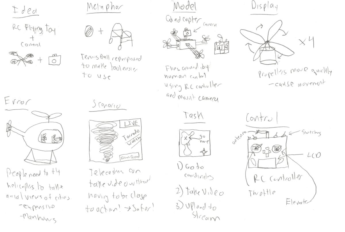
From there, I made a few quick sketches of some designs I considered for my quadcopter. Below is an example of one of my sketches.
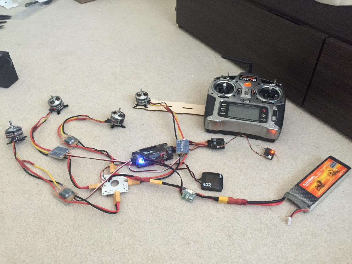
Next, I researched on the different parts I would need and the pros and cons of each one. I came up with the following list of parts I would need. Note that this list has links to professional sites with product descriptions. Some of them (like 3DR) sell these at ridiculously high prices, and so I would urge you to look into other options.
One of the biggest components I felt was missing from a lot of guides is simply an explanation of what each part does and why the decision was made to choose one part over another. I want anyone who reads this guide to be able to make their own decisions when building their quadcopter, rather than just blindly following what I used or by just using a kit. Though there is nothing wrong with using a kit or just using all the parts I used, I found it to be a significantly better learning experience to understand what each part did and make my own decisions rather than just trusting what others have done without understanding why.
The APM is our microcontroller. The biggest reasons why I chose this are that
a) It is simply an Arduino Mega with some sensors and libraries
b) It is very mature technology.
c) It has been tested heavily.
d) It is reliable and trusted by many users
The APM comes with a 3-axis gyroscope, an accelerometer, and a high-performance barometer. To put it simply, it is the brains behind the machine. You can find these for~$60 on eBay.
The APM power module allows you to power your APM safely using a LiPo battery. Since the optimal voltage of the APM is 5.3V, and a LiPo battery often provides more voltage, the APM power module acts as a voltage regulator, ensuring that the APM only gets 5.3V from any LiPo battery.
The GPS module with Compass gives you the ability to lock on to a GPS location, and use that location as a point of access. This allows the adding in of the functionality where the quadcopter can return to home, or go to a certain waypoint. More importantly, however, the external compass this GPS has is required for the APM to arm. Prior to APM 2.6, a compass was installed within the APM (similarly to the gyroscope, accelerometer, etc.). However, due to issues that some users had with interference, APM 2.6 and onwards require external compasses so you can mount them away from electronics that may cause such interference. You likely can choose any GPS you'd like for your APM as long at it is compatible. I got this as a set with my APM from eBay, which is why I am using this.
Because the APM is reliant on its sensors, it is important to minimize any interference on those sensors that can be caused my vibrations. Now having four brushless motors running causes quite a decent bit of vibration. Even though wood is a natural vibration dampener, if you were to touch the center console with the motors turning, you would absolutely feel the vibrations. Hence, if you get an Anti-Vibration mount, this reduces, if not removes, any of those issues that the APM might have. Some people swear by anti-vibration mounts, while others say it is unnecessary and to just use some foam. Since they are so cheap (~$5), I figured I might as well get one to be safe. Now there are different types of mounts. Here is a great video where he talks about the different types of mounts available. He seems to agree that the mount I used is the best one for my purposes.
This is simply the way to connect your APM to your computer. Sometimes, when you buy the APM, this may come with it. However, other times, it may not. If it doesn't, be prepared to get one. Amazon sells them for pretty cheap, but you can pretty much use any micro-USB cable you can find.
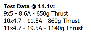
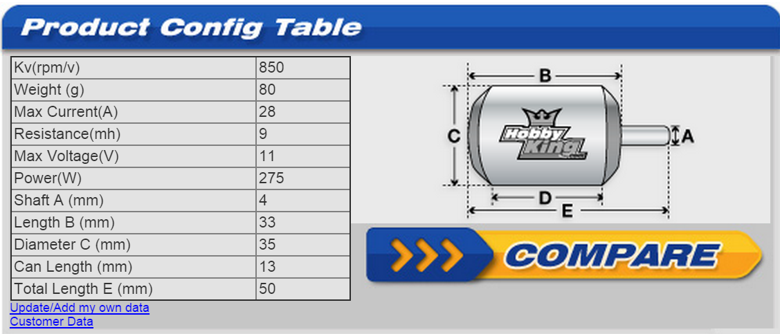
Motor choice is dependent on what you are looking for. I was looking for a motor strong enough to lift my quadcopter easily, not have to be particularly worried about too much weight, but still not use up too much power too fast. For you to make the decision on what motor you want, first lets take a look at what exactly all the terminology means! First you see the '850kV.' This simply means that this motor will have 850 rotations per volt. Now you might immediately think that you should buy the one with the highest rotation--but this isn't usually the best. The reason why, is that though it has less rotations per minute than some motors of comparable power usage, it provides a stronger force to turn each propeller. This allows for use of larger propellers, which transitions to the next point--thrust. The whole point of these motors is to be used with propellers to generate thrust! Typically, you want to take the thurst that your motor will give you, multiply it by 4 because you have 4 motors, and then divide your total value by 2, which is about the thrust required to hover. So for example, if each motor and propeller combo gives you 1000 grams of thrust. You would have 4000 grams of total thrust on for your quadcopter. This means that at maximum, your quadcopter should be 2000 grams to be in the safe ranges.
When I was ordering these parts and planning, I thought about the future and how I would want to probably mount a camera and gimbal onto the quadcopter. I did some basic calculations using known values for birch plywood and so on, and came out to figure that all of that should be approximately 2kg. Looking through motors, I found these motors that would provide me a total of 2280g of thrust when using larger propellers. You can find the exact information on the thrust of each motor from which ever website you choose to purchase from. Here, for example, is the information posted on mine.
I am always a little wary of the numbers they post, hence why I gave myself some extra breathing room of about 280g of thrust.
The electronic speed controllers (ESCs) are required to help change the speed sent to the motor. These also have BECs, battery elimination circuits, which allow you to connect your LiPo battery directly to them without worry. They key thing to note when choosing your ESC is what your motor requests. Typically, your motor will have some information on the required ESC it needs. Mine needed 30-35A ESC, so I went with the 35. One thing I would also look into, that I realized after getting them, is what firmware they come loaded with. Many come with companies proprietary firmware, however, some come with a firmware called SimonK, which was written by Simon Kirby, an enthusiast. As you will see later on in this guide, the comparison shows that SimonK is a much more superior firmware, and significantly affects the stability of your flight. I would recommend searching for one with SimonK firmware, or buying a programming card to allow you to flash SimonK onto your ESC.
Two aspects of propellers are important to choosing the best one for you: material and size. Material is important because it adds to weight, durability, and cost. We are going to want to get 'Slo-fly' propellers because those are ones made for multi-rotors as they fly at relatively slower rotations than other aircrafts. Typically, most slo-fly propellers come in the form of a plastic material, however you can get carbon fiber. Carbon fiber are stronger, but more expensive. I suggest sticking with plastic as they work for our purposes, and if you crash and break a propeller, you can easily replace it. Weight will be important, but it is minimal for our purposes, regardless of which option you choose.
The other aspect is size. From the research I've done, people have found that a larger propeller moving slower is more efficient than a smaller propeller moving faster. For example, one source states that propeller efficiency is related to the amount of contact area a propeller has with the air. Thus, if you increase the propeller length (larger area), the efficiency of the propeller increases! Across various different sources, this seems to be the accepted idea for propeller size. Like I said with motors, however, larger propellers require more current to turn. Also, since they move slower, they will slightly less responsive than a smaller propeller moving quickly. I actually found this to be an advantage, however, because as a beginner pilot, slower makes it easier to control. Because of all of this, and the motor thrust values provided by the manufacturer, I decided to go with 11x4.7 propellers.
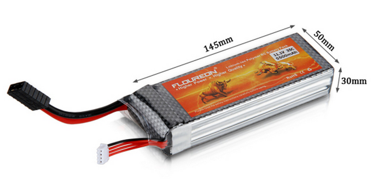
For the battery, the one thing that will likely stay constant is the fact that you need a Lithium-Ion Polymer battery (LiPo). LiPos provide consistent rechargeability, balanced with the best power to weight proportions available. It might be easy to think that you should just get the largest battery available, but the gain in flight time isn't proportional to the weight, and therefore is not the best way to look at it.
One good thing to look it is the battery's C-rating and cell count/voltage. You should match your C rating with the rating on your ESC, as well as your cell count/voltage with the specifications the motor manufacturer provides. My ESCs were 35C and my battery cell count recommendation was 2 - 3 (7.4 ~ 11.1V). As such, I searched for a battery that matches those specifications while still being cheap and relatively light weight.
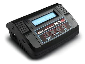
LiPo chargers are relatively straightforward. They typically come in 4-button versions and you can get any. The one word of caution I have is to make sure you get an authentic one. The first LiPo charger I ordered from Amazon ended up being completely counterfeit! I had to run to the store to buy this LiPo charger, as it was the only one they had. Sure enough, it worked perfectly--but you do not need to buy such an expensive one. Others should work fine as long as they are not counterfeit.
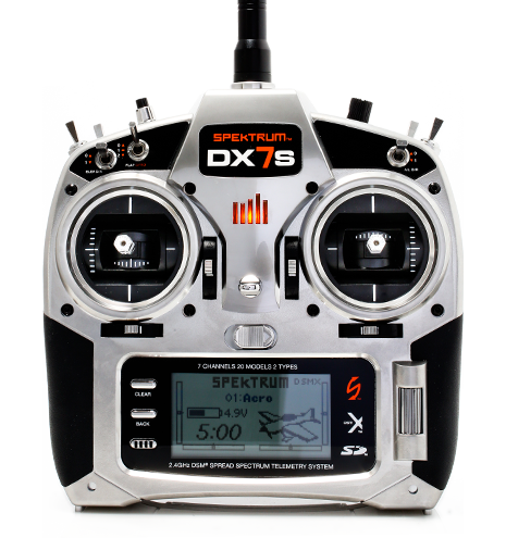
Your choice of RC controller is completely up to you. As long as you get an RC controller that has the two basic sticks and a switch, you should be fine. However, make sure that you get the receiver with it as well! Spektrum seems to sell high quality ones, but they are relatively expensive. I chose this option as I was able to find a Craigslist seller selling this combination for $75, while on Amazon it was $200. Sure enough, it works great--but any controller should be fine. If anything, the real difference will simply be in the feel and the range (which you probably won't hit the cap of anyways).
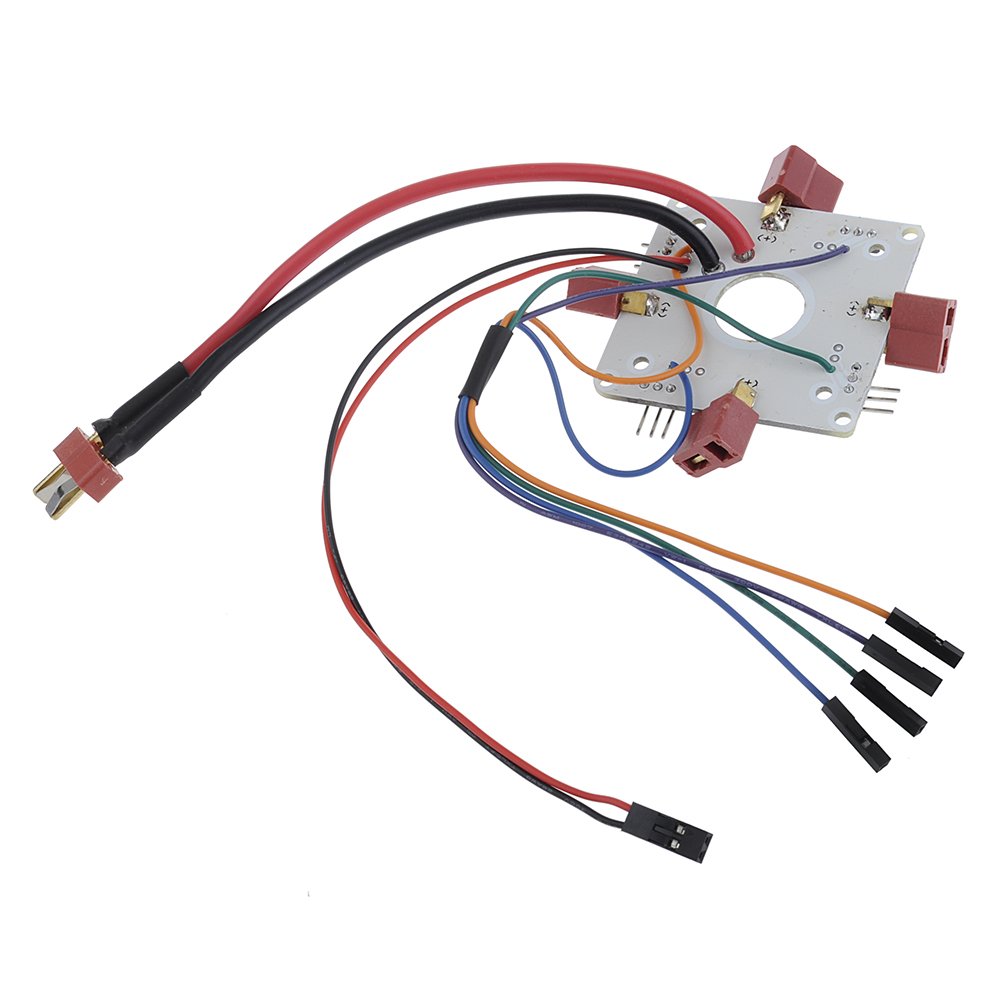
A power distribution board is needed as your APM cannot power your motors on their own. Since only one battery is being used, we need a distribution board to send that power to four different inputs (four ESCs). You can choose to buy this or even just make it--it is pretty simple to do. I ended up doing a mix of each, as is detailed further on in the guide, but if you do choose to buy it, you can find many cheap options(~$7). The only real difference is in the look of it, and the adapters it uses. I have tried quite a few adapters, and I feel that XT60 are the most solid connections, so I would recommend the one I bought.
There are many different options for choice of material. Since I was using a laser cutter, I was mostly limited to wood and acrylic. Of the two, I chose wood as it may be heavier than acrylic, but it is also a stronger material--making it more resistant to crashes. Along with this, wood is a natural vibration dampener, so it will help minimize interference to the APM (along with the anti-vibration mount). Within wood, there are many different options. The two most readily available to me were oak plywood and birch plywood. I chose birch plywood as it is denser and heavier, make my frame more resilient to breaking. It also better to use bolts on than oak plywood. The other option for wood I considered was Balsa, as it is often used in model airplanes--however I realized that it is simply too weak and easily breakable.
You will need some sort of adhesive to connect all the parts of your frame together. You could use wood glue, but I did some research on to the types of glue used for model aircrafts. Cyanoacrylate is a relatively instant glue that only grows in strength over time. It is also lightweight and comes easy-to-apply on thin wood surfaces. I ended up purchasing thin Insta-cure CA, thick Insta-cure+ CA, and super thick Maxi-cure CA. I tested all three on my joints, and found that of the two, thin Insta-cure CA and super thick Maxi-cure CA worked best. Of the two, Maxi-cure would cure quicker and was great for filling gaps, while Insta-cure was better at applying to seams and holding it there. Though Insta-cure has a shorter cure time, it took about 10 extra minutes for it to cure enough to hold the pieces together. Even so, I felt that the joint made by the Maxi-cure was stronger, and just ended up using Maxi-cure throughout. It is a great product that works quite well. I absolutely would recommend it. The company you get it from isn't that big of a deal. The common one found in hobby shops is made by Bob Smith Industries, and is simply repackaged with other names on it.
You can argue that this is not necessary, but I would say that it absolutely is. CA glue cures very fast! And no matter how careful you are, there is a chance you will make a mistake. Having a debonder available is important because it gives you the option to undo joints. Don't expect, however, for this to be easy. Even with the debonder, since we are using Maxi-cure, it took me about an hour to undo two joints. I even had to user a small blade to try and separate the joints so the debonder could make it to the middle. One key thing to note, don't use it on your skin! It won't harm you in any way, but it really isn't that effective. You likely will get glue on your fingers while putting everything together. The best way to deal with this is to wash your hands with hot water, or take a hot shower. Using the debonder on your skin will work a little bit, but I found it to be pretty ineffective. On top of that, it will de-fat your skin, making it wrinkly for at least the next few hours. If your fingers are stuck together and you have tried washing them, you can use a little debonder, but other than that, I wouldn't recommend it. Because we are naturally always shedding skin cells, the all the bits of glue remnants that are on your fingers will be gone after about 24 hours and a shower.
Design Process:
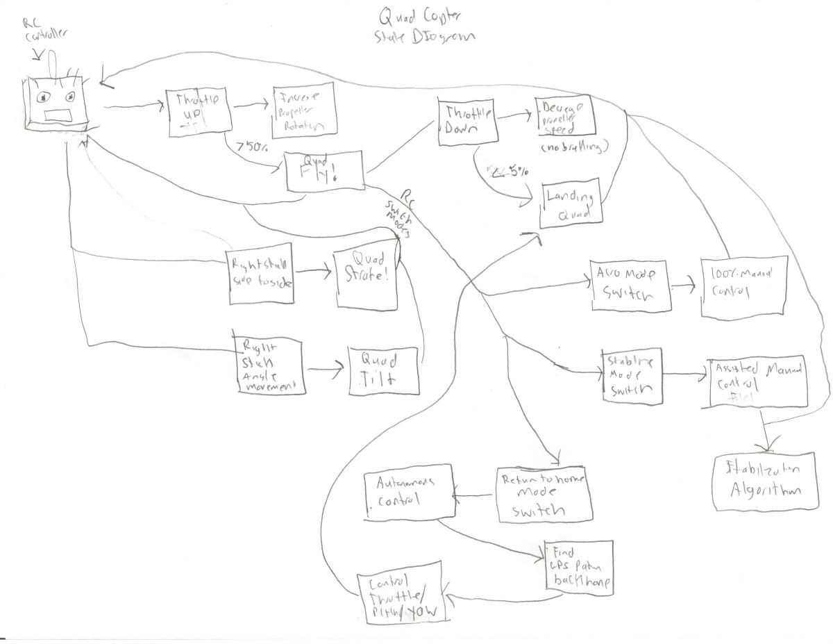
I started off my design process by thinking about the different basic actions I would need my quadcopter to do. I thought of them as states and came up with the following diagram:
Keeping this in mind, I decided to set my design focus on a quadcopter that could achieve those states and be able to be built using a laser cutter. The reason I chose a laser cutter is that, though I have access to 3D printers and laser cutters, I am only familiar with using laser cutters. Since I had about a week and a half to build all of this, I decided to stick with what I know for now, but build it in a medium that could be transferred over to 3D printing without too much difficulty. The natural option was to go with Solidworks as it would give me both options. I did, however, still try and keep my designs oriented towards a laser cutter.
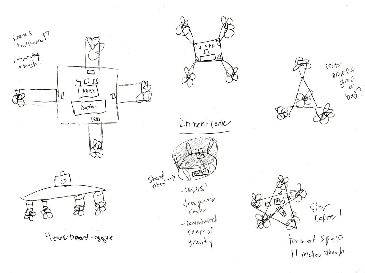
I brainstormed a lot of ideas, and I started moving my sketches to Solidworks to see them visually. Through the process, I came up with a total of eight Solidworks designs.
For example, one of my early designs for the quadcopter was something like this:
Not all my ideas were as serious--I wanted to explore my options and try different things! One of my wackier designs was something like this:
What seemed to be the general idea I had in my head was that I needed to have four equidistant propellers with a place to mount the motor, and a center console where I could put all my electronics and wiring. Taking a step back from the drawing board, I tried to look at the design from a more practical sense. How would I best get this to work? How would everything fit? Quadcopters fly around and are prone to crashing--how can I keep my electronics safe? I went on to think about a design where I had 4 enclosed arms, with a square center console. However, I realized as I was trying to mock it up that the arms would have to be really long to give decent space between each propeller and the center console. I moved away from a square to a more octagonal shape, as it would give me the the length in places where I needed it (particularly for the battery) while having a curve-like structure that cuts off the edges of a potentially unnecessarily large rectangular prism, while still being laser cuttable. I also realized that if I split the octagonal piece into two layers, I would save space and wood (thus have less weight overall).
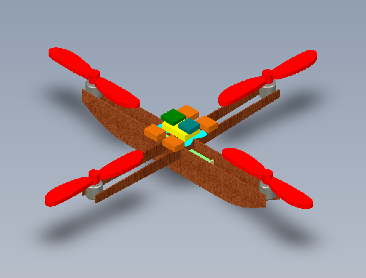
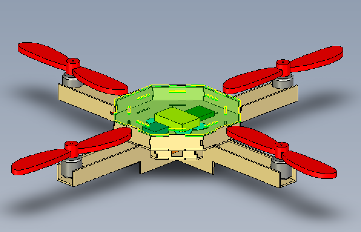
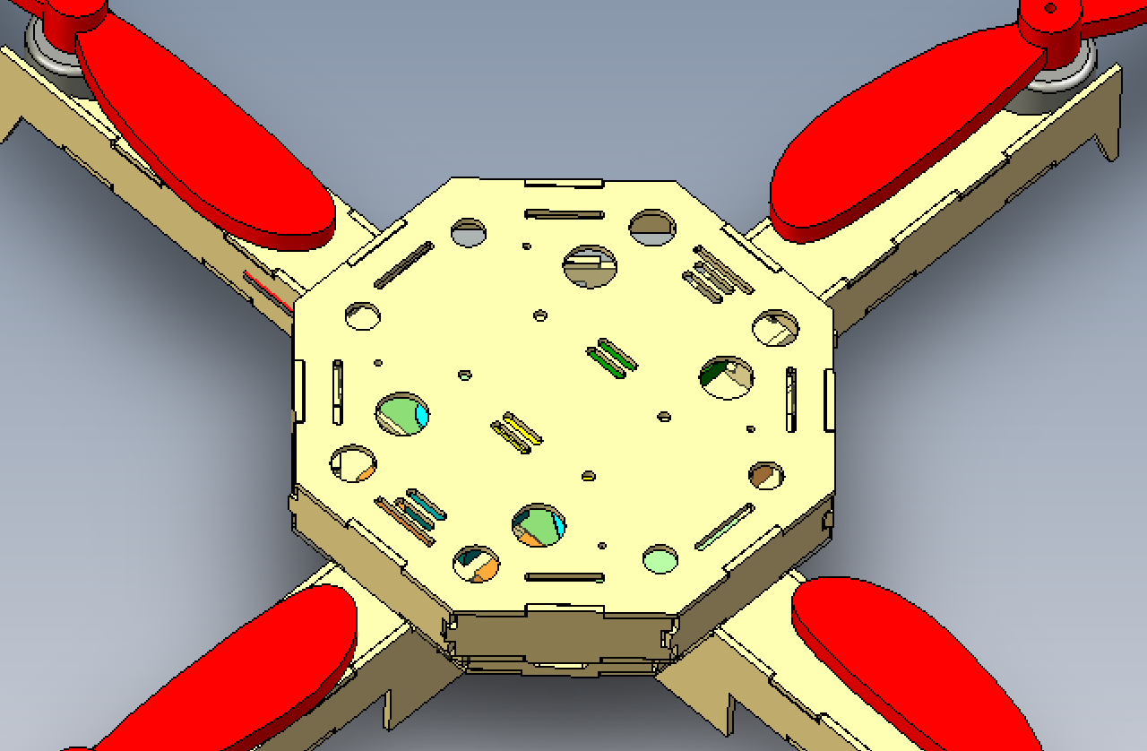
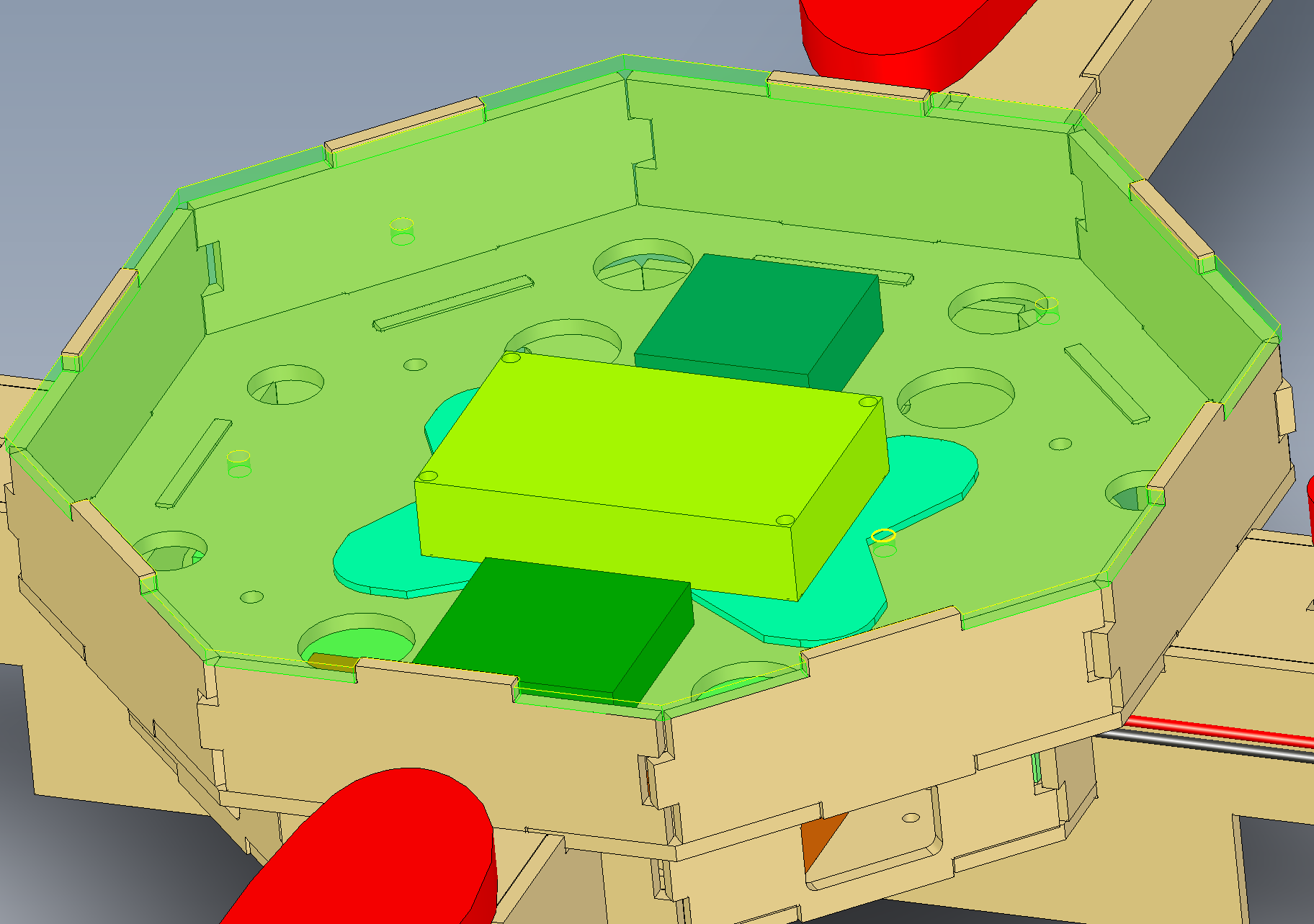
This is when I came up with a this design, which is what my final design is then based off of:
This view is with the edges shaded to show how the wood would piece together. Here is a view where you can clearly see the two layers with the top being transparent:
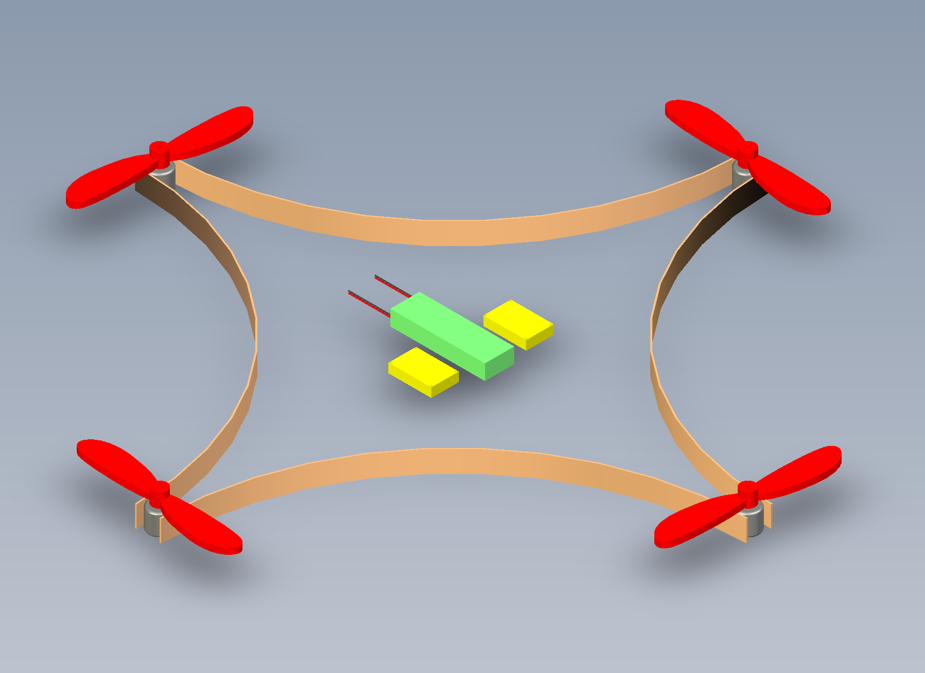
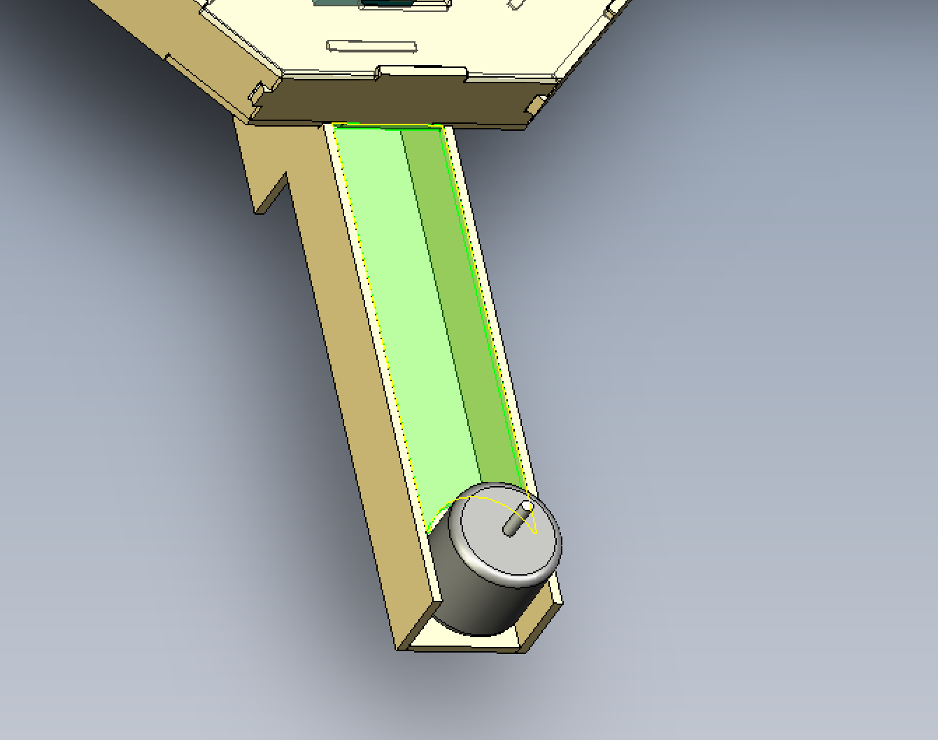
I was actually quite pleased with this version. But I still wanted to improve on it. If we take a closer look at the arms on this design with the propeller removed:
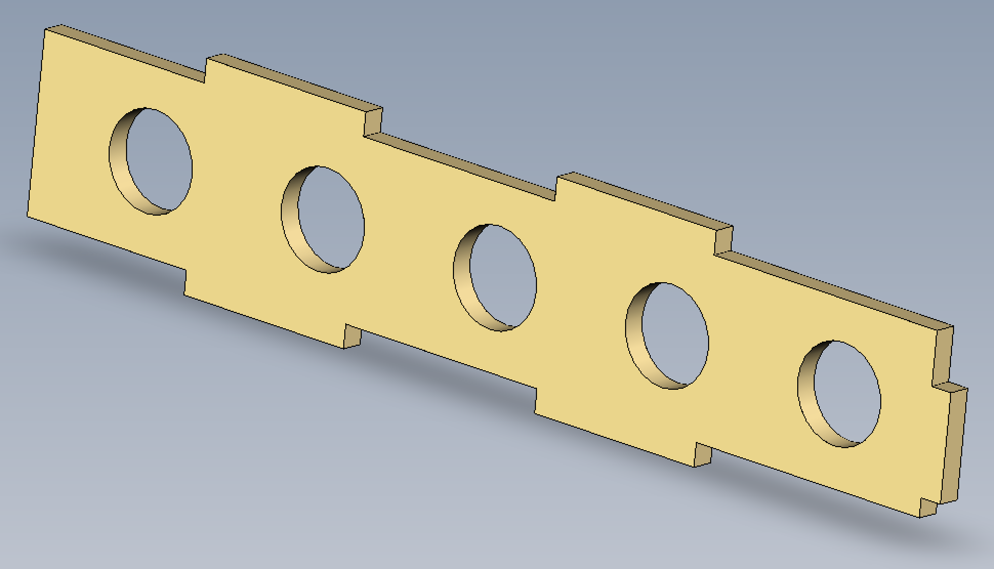
you can notice that it is a simple hollow rectangular prism. I figured that a long hollow arm may not be the best structurally, especially since this will probably crash often. I decided to make a sort of I-beam in the arm, to not only help it structurally, but also provide a nice divider for my wires. My I-beam piece design ended up like this:
and would fit into my arm like this:
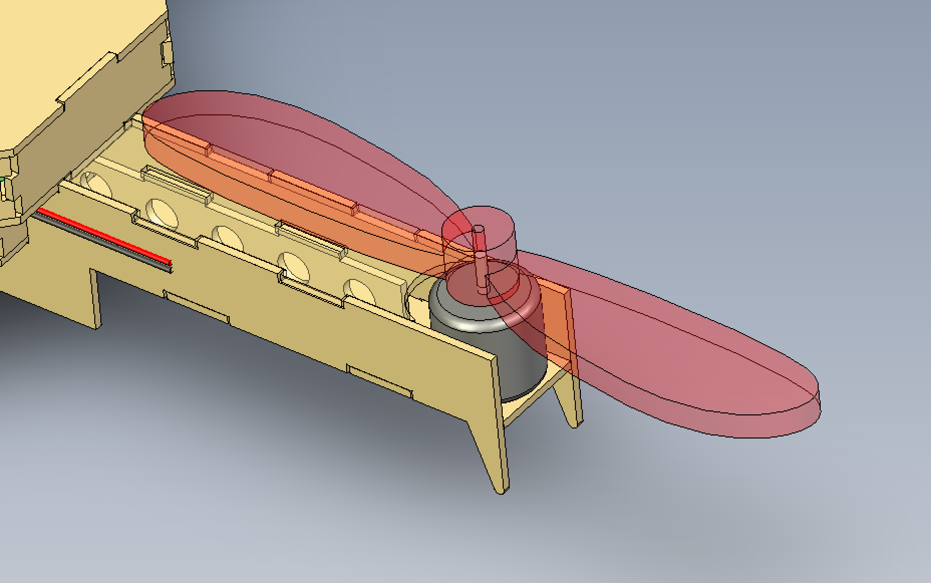
You'll also notice that in this design, I decided to add little legs at the bottom, so that when it lands, it doesn't just fall flat onto the arms. After this, I thought about how I would hold all my electronics down. I figured that I would use zip-ties, and so I made holes on the center layer that would be convenient for use with zip-ties.
I quickly realized, however, that having holes on the top layer would not be useful, as I would not be mounting anything on the top. I, thus, removed those holes.
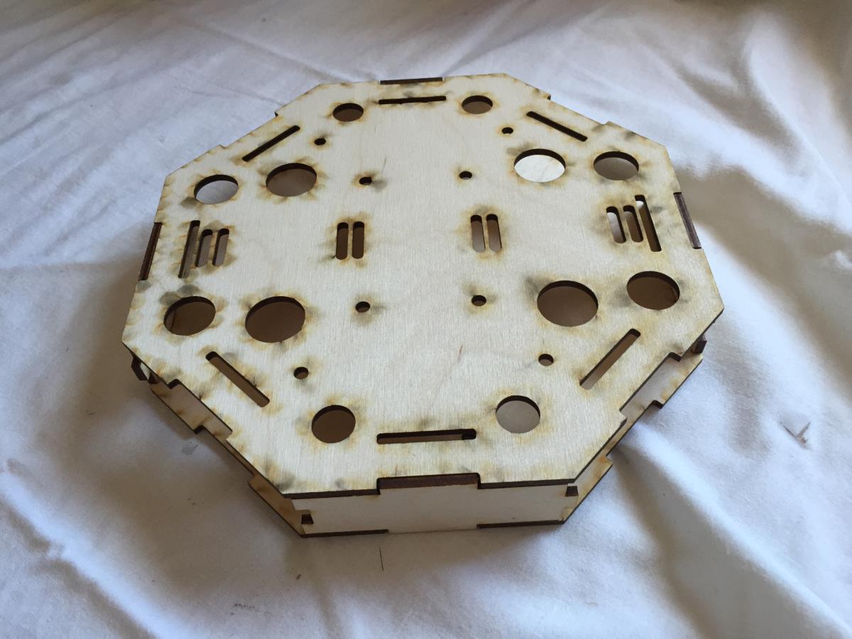
However, you may notice that on the top layer, I left four small holes. These holes actually go all the way through each layer. One design aspect I was pondering for a while was how I would make these layers accessible. I obviously would need to be able to access all these parts as I may need to make modifications. And if not that, I'd at least need to be able to charge the battery! I thought about one Idea where I would make one to two sides of the octagons with slits to act kind of like sliding doors, but that proved to be difficult to create with a laser cutter, and also unreliable. I took a step back and realized that I may be overthinking it, and so I simply put four holes straight through all the layers, to hold them together! The layers are already designed to fit into each other... the screw would just hold it in! Whenever I needed to access it, I'd just remove those four screws, and I'd have access to every layer! Also, if you are wondering about those larger holes in the center layer, those are there simply to wire cables between the layers. Some of the plugs I looked at seemed pretty big and I didn't have the parts on me at this time because I was waiting for them to ship, so I put those holes in to allow wires to easily pass through each layer.
At this point, I felt ready to move to laser cutting. At this time, it was around Sunday, and I planned to be working with the laser cutter through Monday as I expected there to be a rush for use of the laser cutter. Also, I finally expected to get my parts by Tuesday. This is the design I went in with:
Unfortunately, after laser cutting the entire design and fitting it all together, I received my motors only to find that the retailer had completely lied about its dimensions. The retailer provides the following dimensions on the motor:
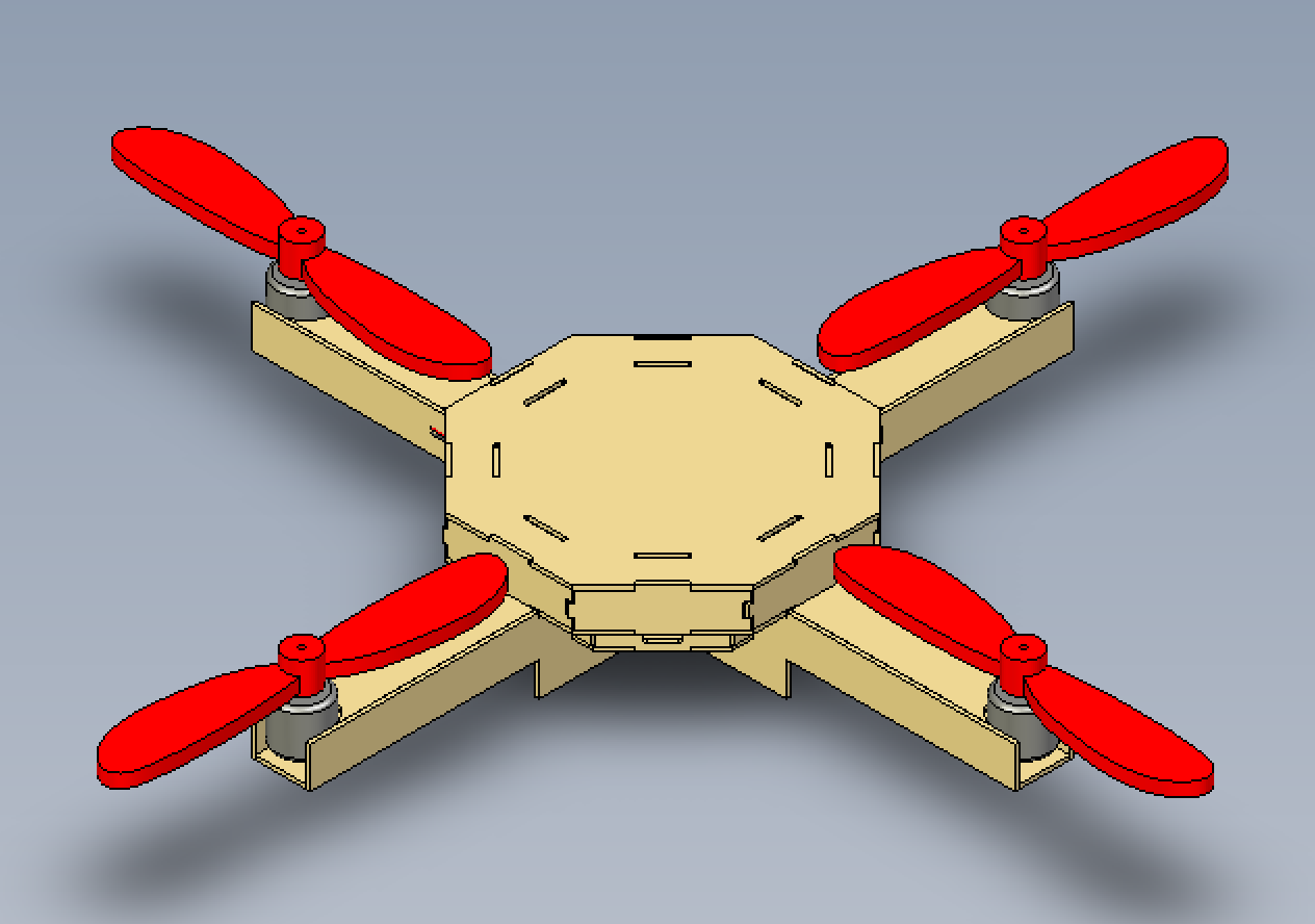
These are great, but they do not help me too much because they don't give the dimensions of the motor mount, which I need to know get my arm sizing correctly! HobbyKing, the retailer I bought the motors from, doesn't have a phone support line, but they do have a live chat. I contacted their live chat, and a "Product Specialist" gave me dimensions for the motor mount. I confirmed with him a few times that these were exact. He swore by his measurements and said, yes absolutely. Much to my surprise and despair, they absolutely were not the measurements. Honestly, they were not even close! Taking some calipers, I measured every single piece of the motor mount, and went through a few more revisions to finally get a working version of this motor mount. I had to increase the arm width, but also accordingly change the tab sizes, and even how it fits into the entire center console. To ensure that I had it right this time, I pulled the 2D file into Illustrator and printed out just the arm base piece with the motor mount holes 100% to scale. I then cut it out and made sure it aligned with my motor mount. I adjusted from there until it fit perfectly, and then I went again to the laser cutter on Wednesday and got my now final design cut out. This is my most up-to-date Solidworks model:
An issue I ran into for Wednesday, that makes this who motor sizing problem slightly better, was that I wouldn't be able to start on my wiring anyways. 3DR was supposed to send me the power module I needed for my APM, however, for some reason, despite ordering 7 days prior with 2 day shipping, they simply did not ship it! I called them 5-6 times trying to sort out this issue and only after the 6th call was this resolved. Quite literally, the entire issue was that I was a new customer so they wanted to confirm my address and billing information. However, they seemed to neglect actually calling me or emailing me to do that! I ended up receiving the part on Thursday, despite the fact that 3DR is based and ships from California, right near home!
Laser Cutting Process
The laser cutting process was relatively straightforward for me as I had become familiar with it earlier in the semester. That plus the fact that there were surprisingly few people waiting for the laser cutter made both experiences pretty seamless.
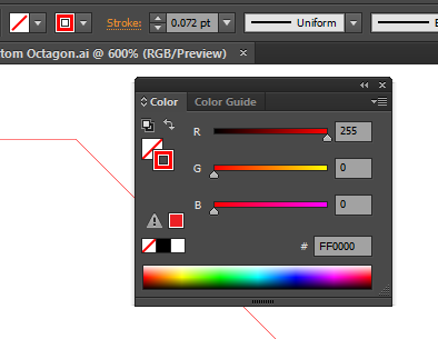
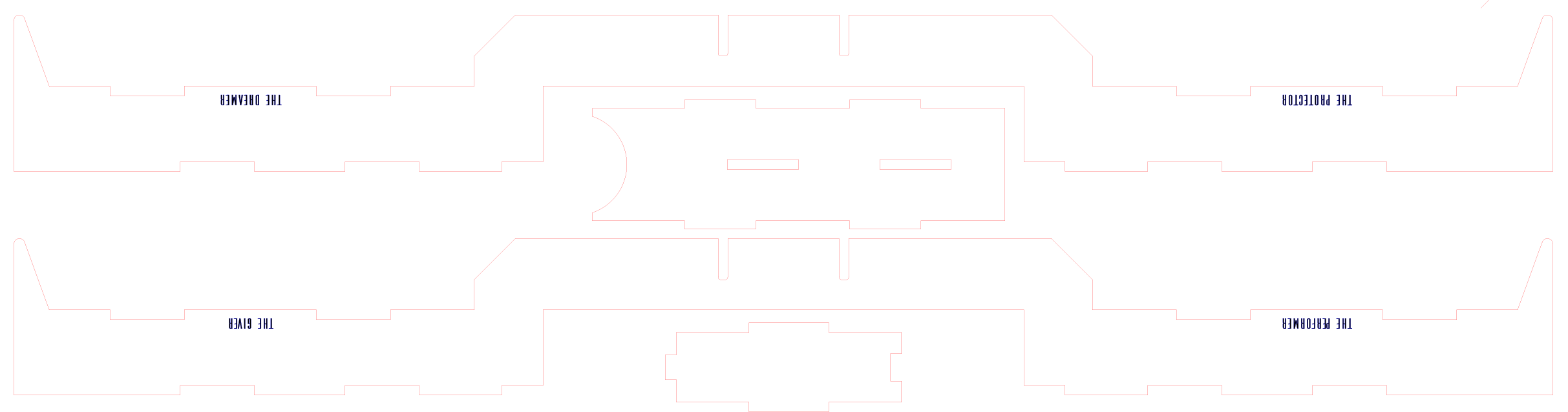
I prepared my files for laser cutting by first switching into 2D view in Solidworks and saving files as such and saving them as .DXF files. I then opened them up in Illustrator, set the stroke width for all the parts to be 0.072 and converted the document to RGB. Since all of my lines were cut lines, I made them all solid red: RGB(255, 0, 0).
The 2D conversion from Solidworks spaces all your pieces out nicely. I however, also ended up decreasing the spaces between all the pieces as that much space was not needed for the laser cutter to do it correctly.
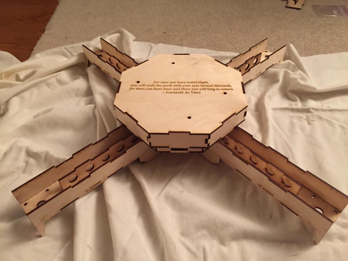
I also added a few aesthetic details to the design. I added the quote:
as it seemed fitting for the project.
If you look closely you can see a small blue outline around the text. This is added to give a certain "pop" to the text, as it will first raster all the text on, then engrave the outline of it.
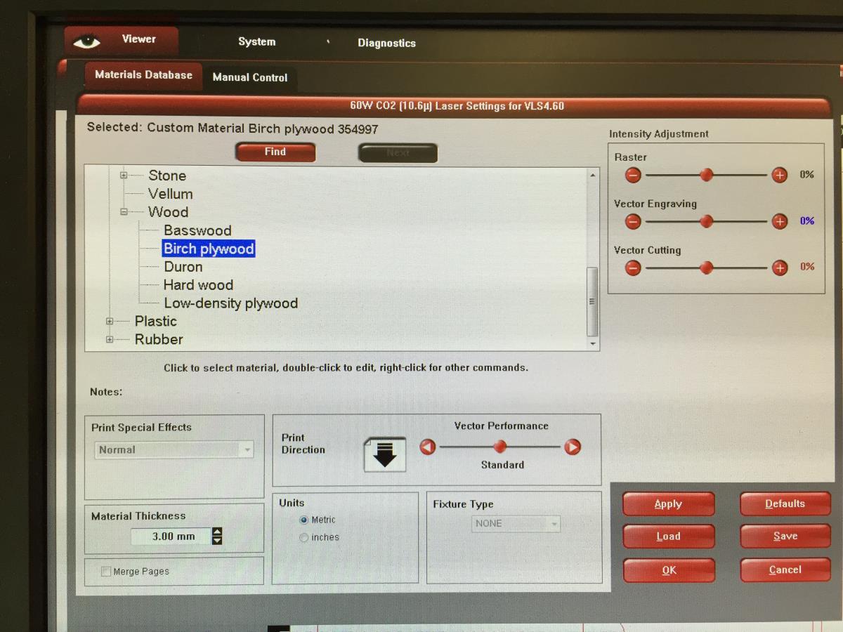
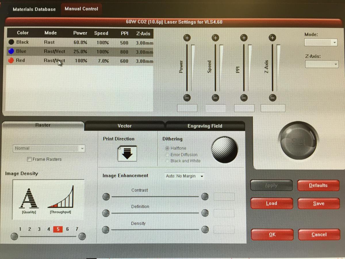
Once at the laser cutter, I made approximately 20 test cuts over the period of two days to make sure I had the calibration right. The reason I had to make so many was because the lab techs advised me that the laser may need different calibration at different points on the cutter. Since I was using a 18" x 24" sheet for one of my cuts, which is the max size for the laser cutter, I had to make sure that it would cut at all points. These were the laser settings that worked best for me:
Under Manual Control:
And of course, here is the laser cutting process itself (fast forwarded):
Frame Assembly
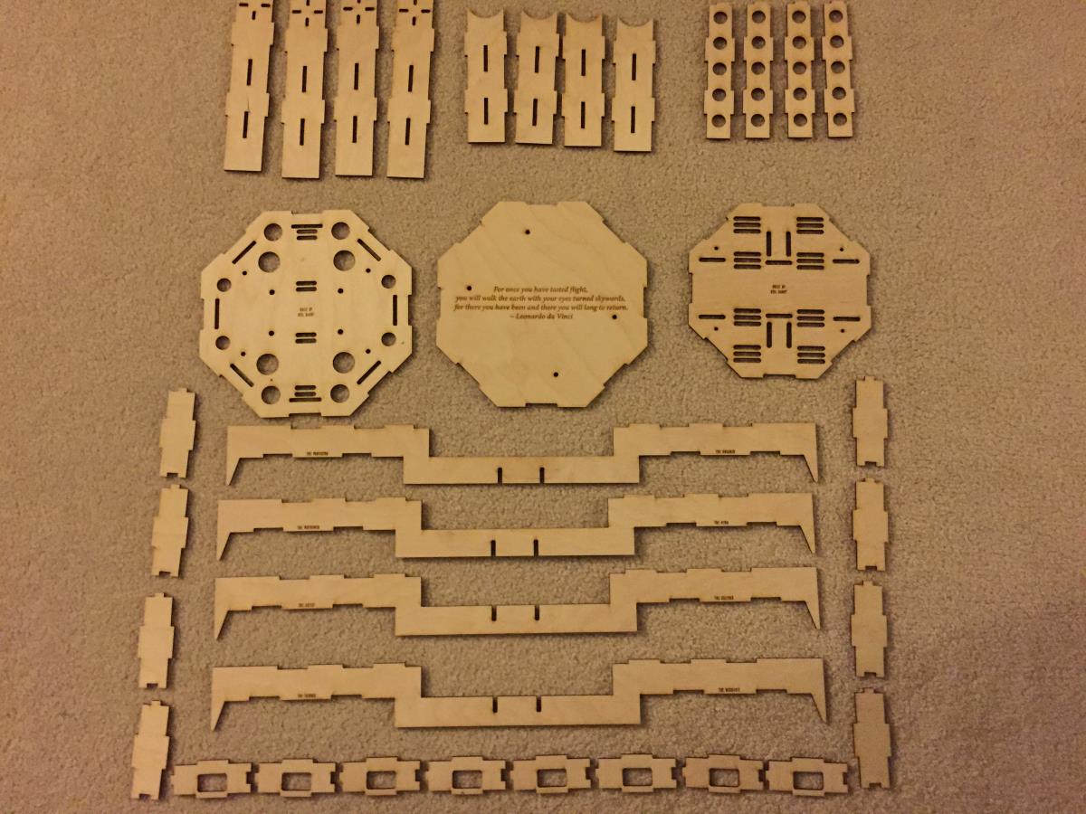
Here are all the parts we have to work with--freshly laser cut!
Important note: the order in which you assemble this matters! As you will see through my process, I initially assembled this in the incorrect order, and I had to spent a nice chunk of time decuring the parts, and reconnecting them in the correct order.
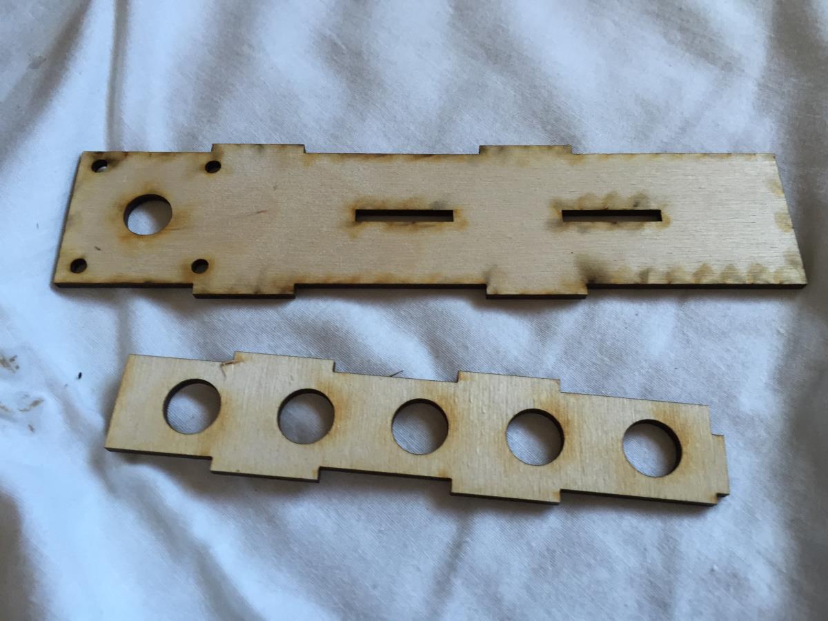
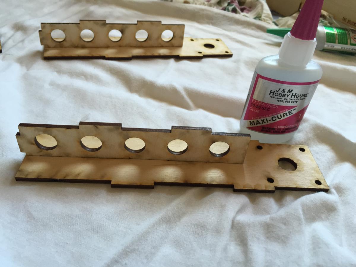
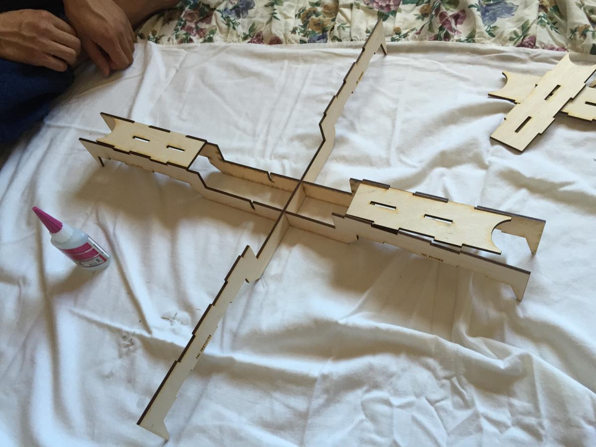
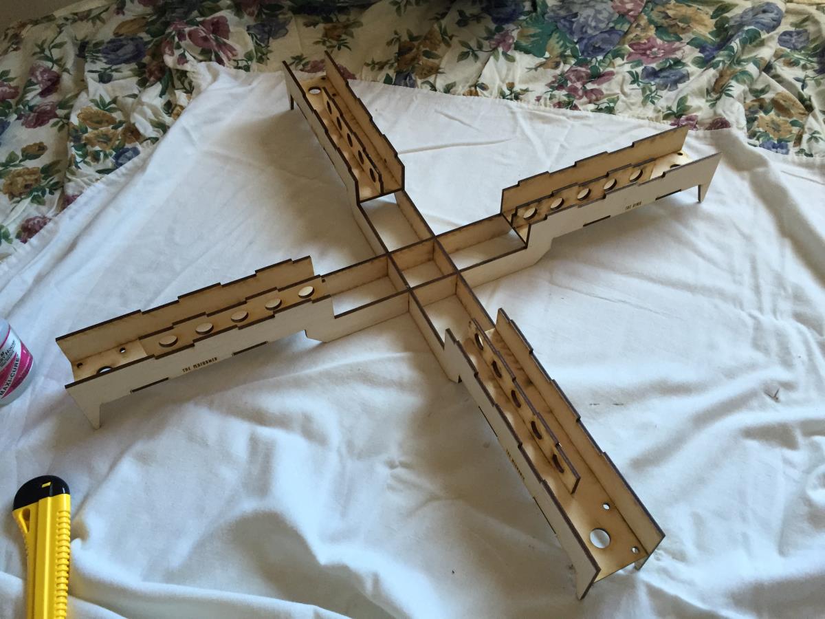
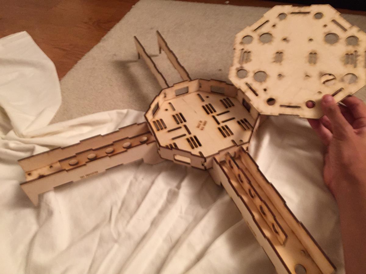
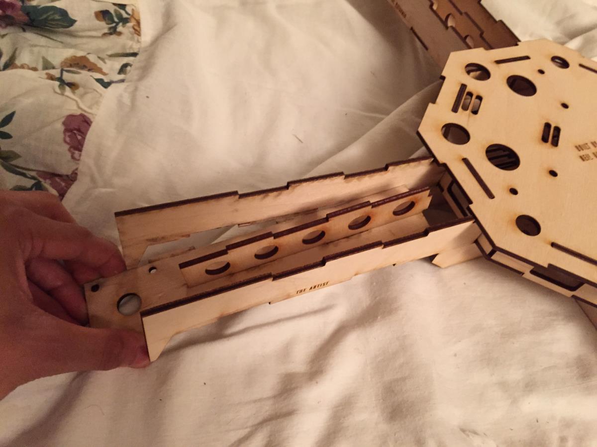
The first step is to take the bottom pieces of the arm, and the I-channels and glue them together using the Maxi-cure CA adhesive. I suggest laying this down on some old bed sheets as I did so that the glue doesn't get on the surface you are assembling on.
I like to the keep the side with the laser burns on the inside, and keep the nice clean wood on the outside.
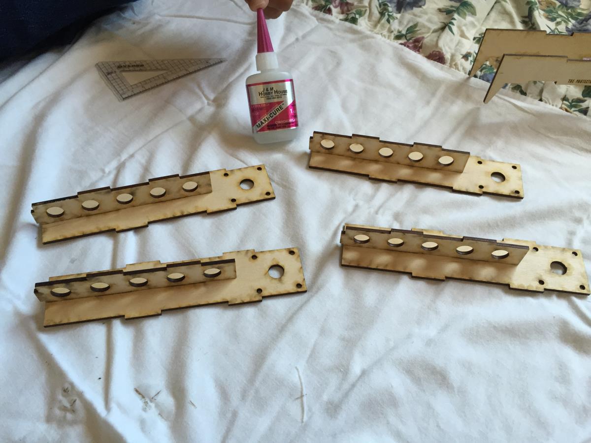
Glue all four pieces together:
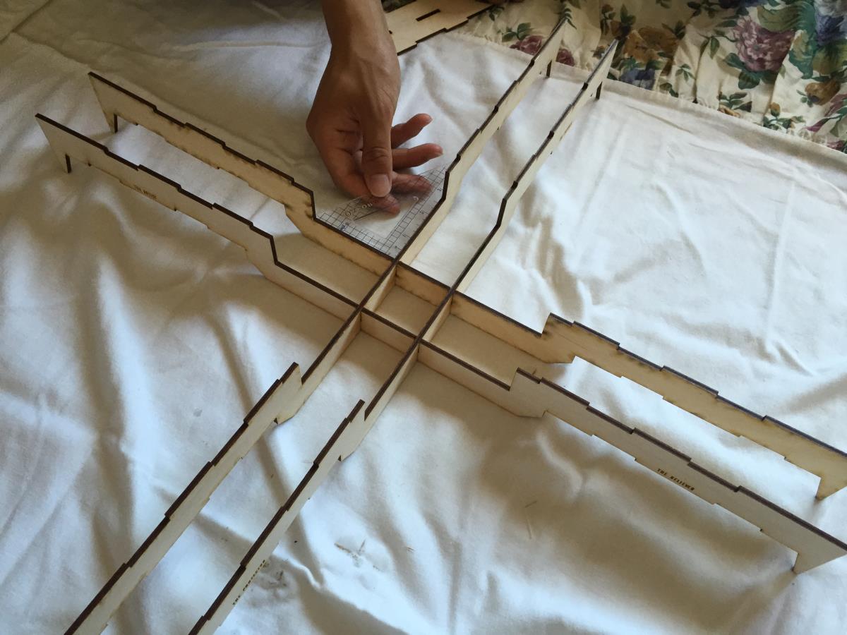
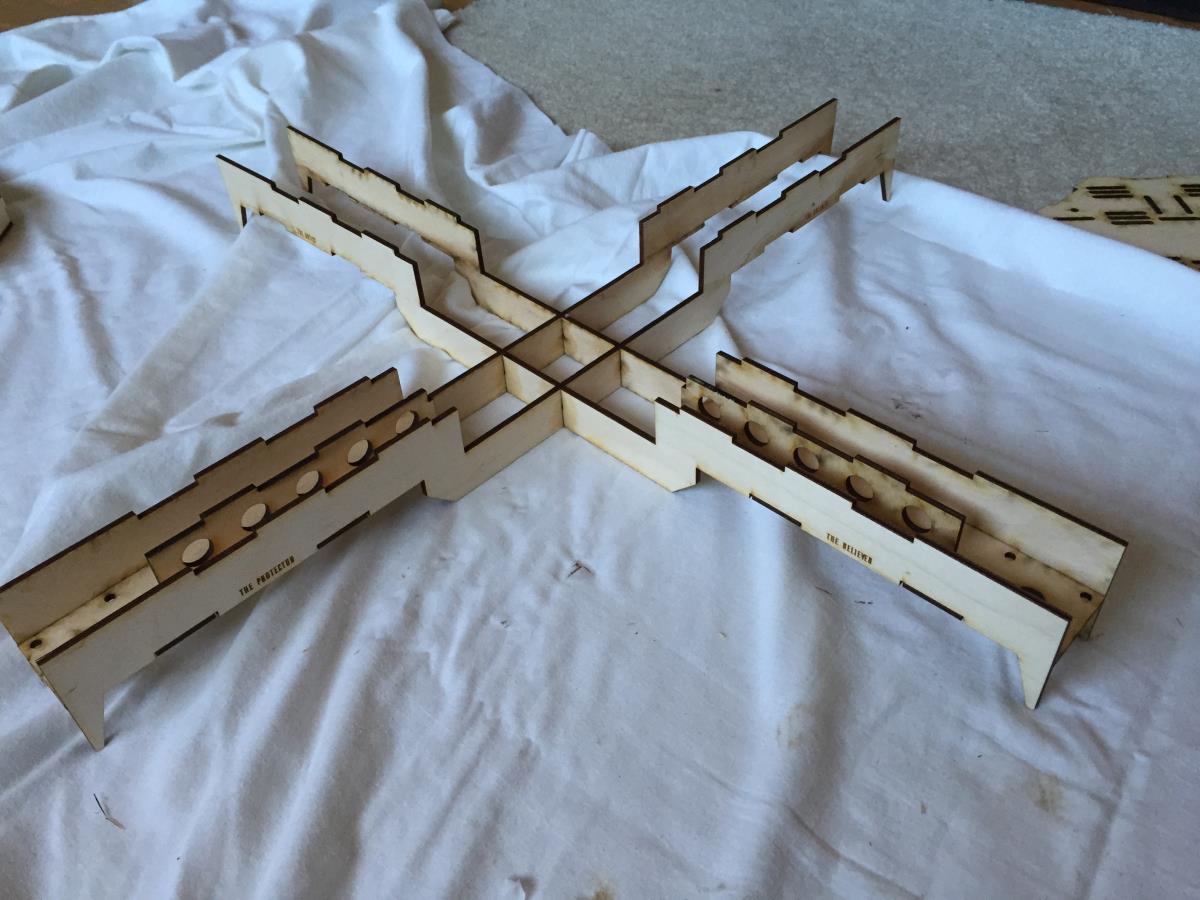
Next, align the wing pieces together and use the arm tops to make sure they are aligned correctly:
*if using my design, you should notice that all the writing is facing outwards.
Now simply glue the wings together. I applied the Maxi-cure CA adhesive on the parts that were going to push together and then held it there for 30 seconds.
I used a set square to make sure the angle was 90 degrees.
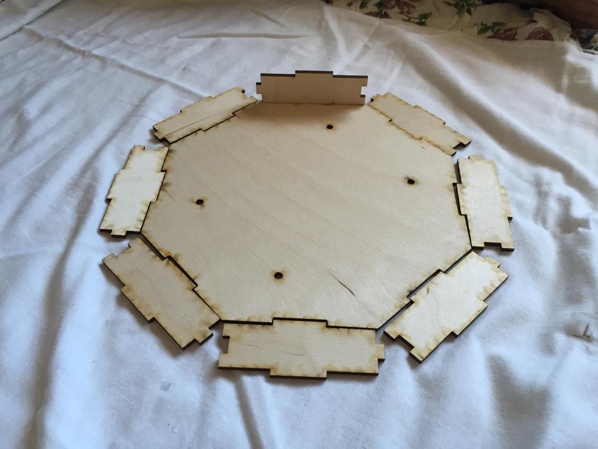
Now, while we let that CA sit and cure, we can glue together the top layer of the center console. It will align like this:
First, glue together the straight vertices of the octagon. This makes the gluing of the angled vertices much simpler.
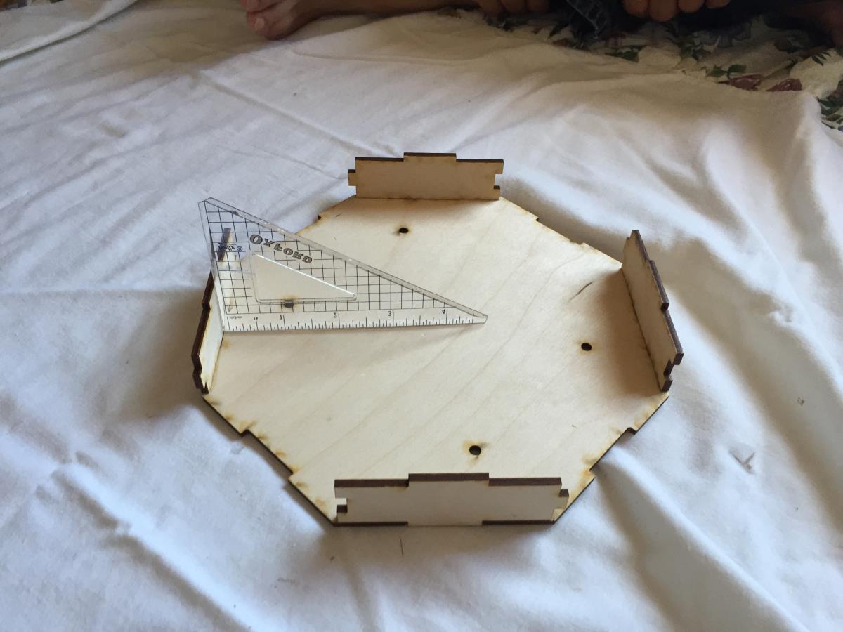
again, I used a set square to make sure that my parts were at 90 degree angles.
Now just glue on the angled sides. These should fit in nicely.
While it is sitting to cure, I fitted the middle layer on top of it, so that it glues in the correct position to easily fit into the middle layer. Do not glue the middle layer to this top layer. Simply just fit it in the holes (it should fit it in comfortably but snugly).
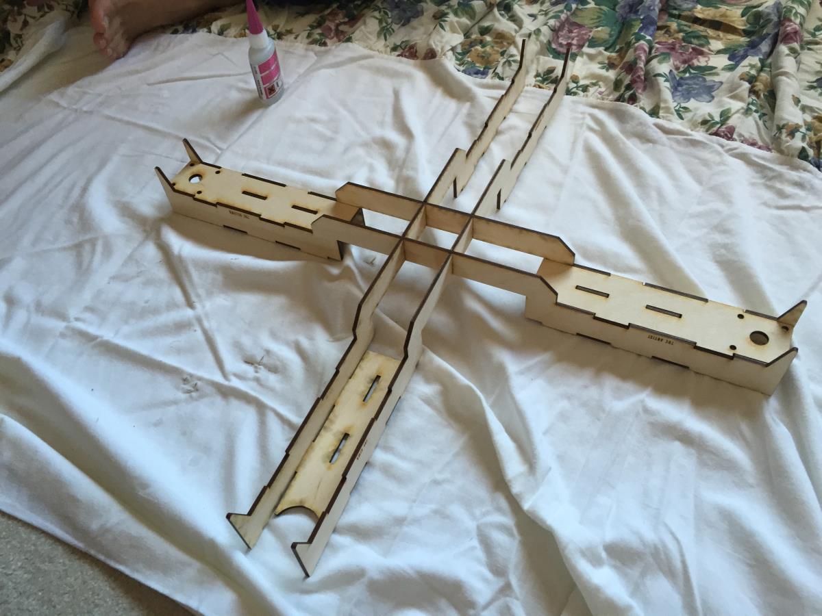
Now here is where I made my mistake in assembling the pieces. Do not do this next part. I spent two hours trying to debond the pieces I messed up. Trust me, Maxi-cure is called "Maxi-" for a reason. This is not a mistake you want to make.
So what I incorrectly did is that at this point, I glued the bottom pieces of the arm on:
The issue with this is that the center console has slots for the I-channel to fit in to. If you glue all four of the bottom sides on, it will be physically impossible to fit the I-channels in the slots, and it simply won't assemble. I made sure to design this frame in such a way so that all the pieces fit together in slots snugly. This allows it to hold together very nicely--however it also makes it a nightmare to assemble if you don't do it in the correct order.
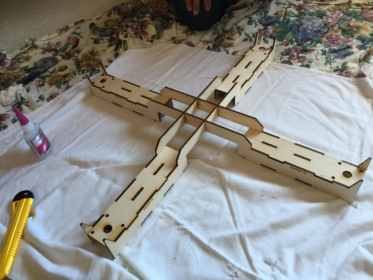
The following is the correct next step:
Glue two legs which are adjacent to each other on:
Next, just click in the bottom layer, and fit in two of the bottom-side pieces to make sure they fit. Here you will notice what I am talking about with the I-channels clicking into the center console.
Just like with the top piece, glue the tabs to the "straight" (so to speak) vertices first.
And then, of course, glue the angled pieces on. They should fit together nicely, similarly to how the angled pieces fit together when connecting them to the top layer.
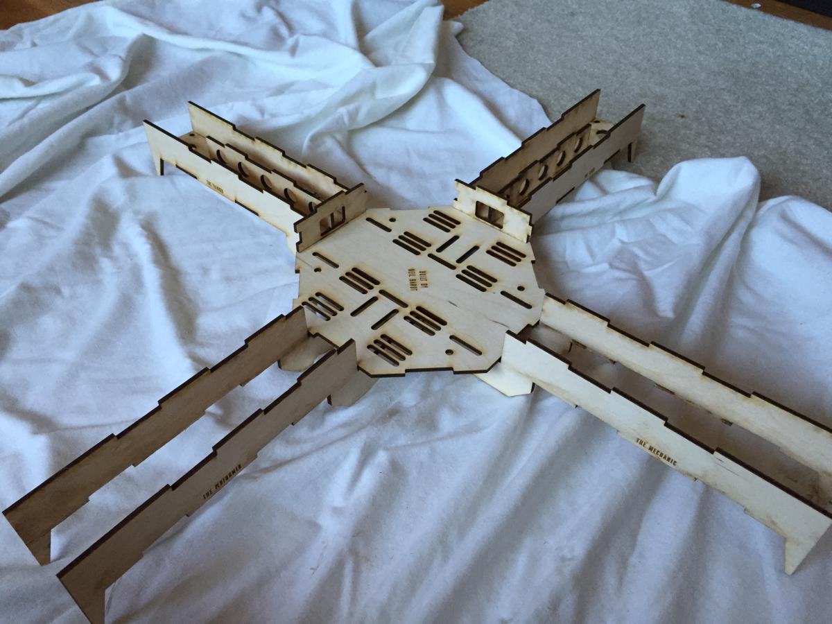
Let this sit for a little bit with the middle layer on top (not glued) so that it can cure completely. After that, glue the remaining two bottom pieces of the arm on. You will have to fit them in at an angle, as shown below.
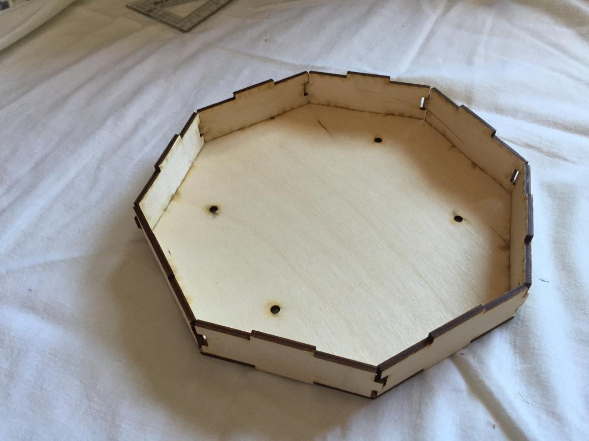
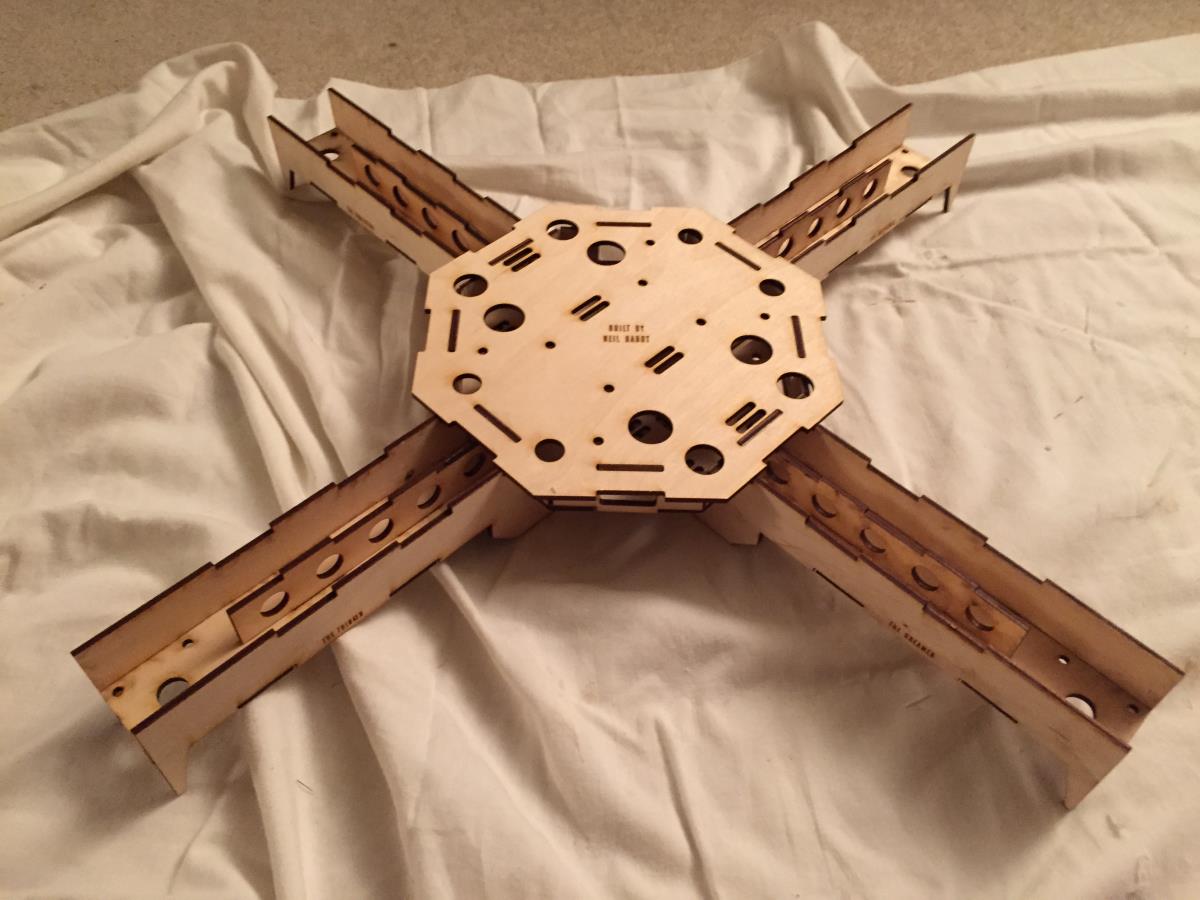
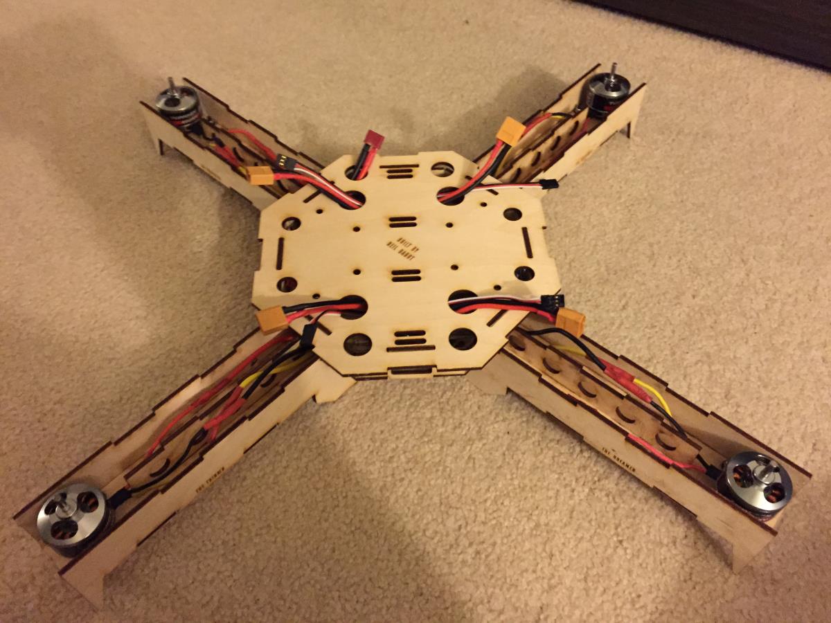
You should end up with this:
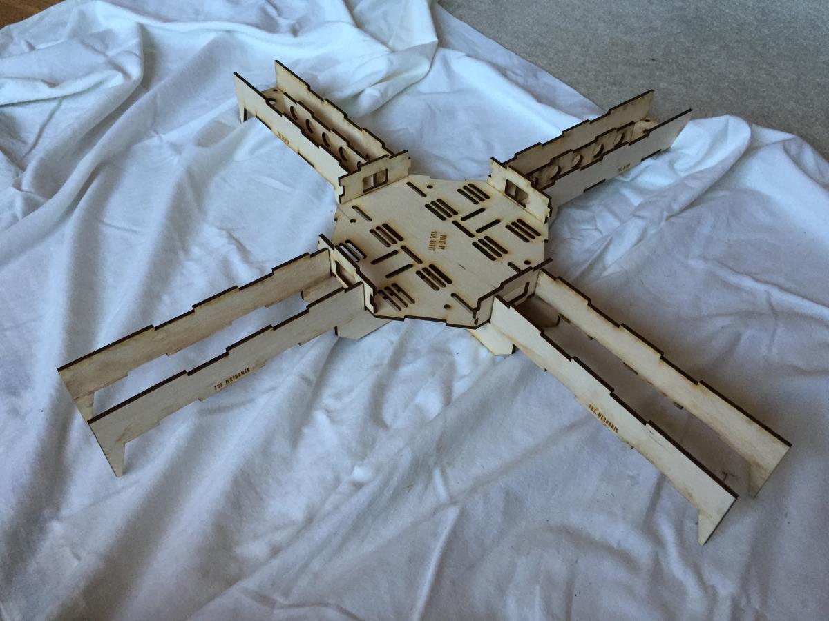
Fit the top on (no glue) to make sure it fits. It should connect snugly, as does everything else. This should be the finished product:
You may be wondering why they arms are still exposed and why I haven't attached the tops. The reason for this is that you will need to connect the motors into these arms/wiring through the arms, and if you attach the tops, you won't be able to do that. We will do that at the end once the quadcopter is fully working. You can, however, fit them on top without glue, as they should fit into the slots.
Microcontroller and GPS Setup
Now we can move on to set up our ArduPilot Mega 2.6! I will refer to it as APM from now on.
First, take your microUSB cable and connect it to your APM. It should light up when plugged in-similarly to an Arduino Micro.
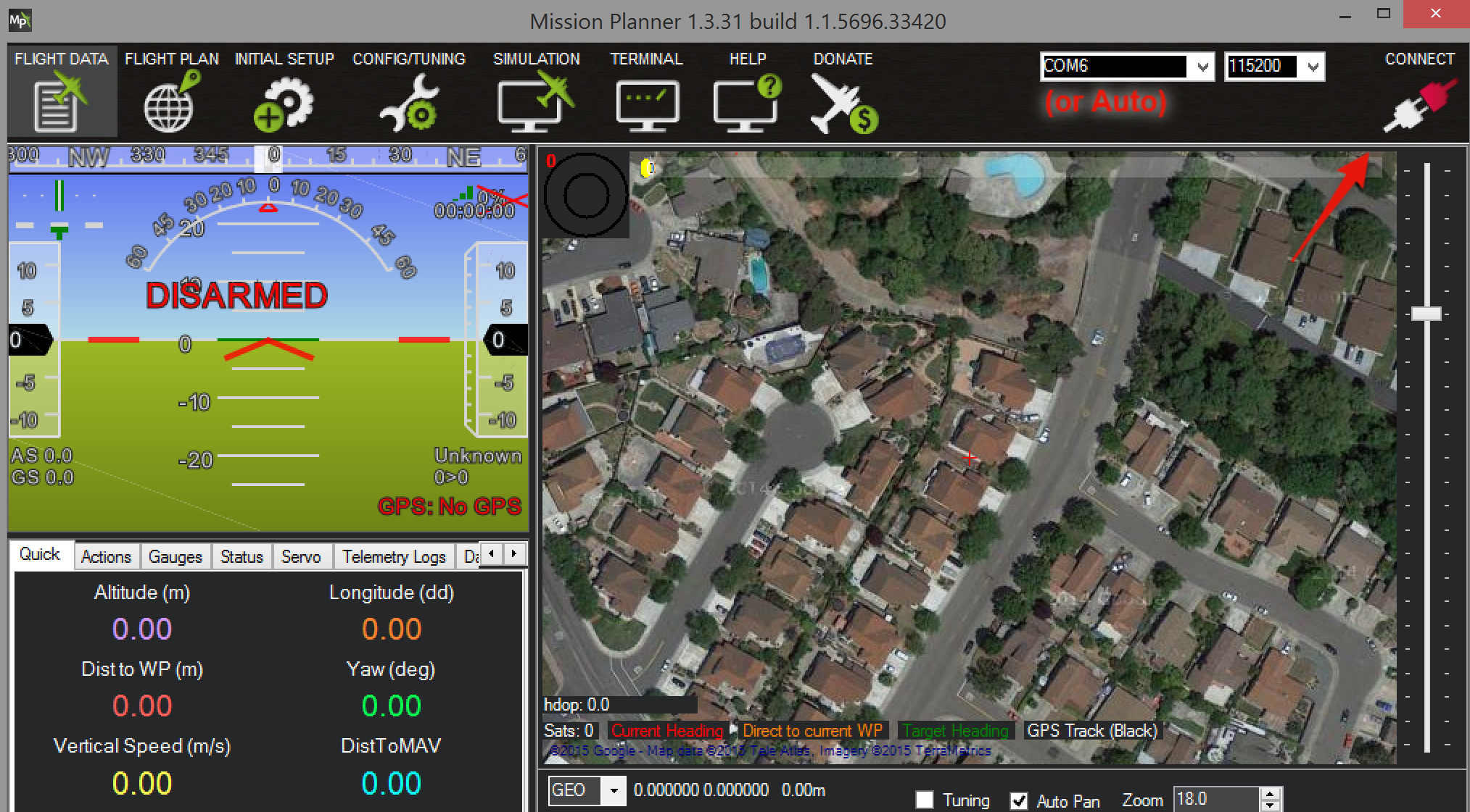
Go to the Mission Planner download page and download the latest version. Mission Planner is a GUI interface that Michael Oborne made to interface with your APM easily. This seems to currently be the most user-friendly approach to setting up your APM. You can use other tools or work with it straight through code (I did that initially)--but for a beginner, this is probably the best option.
Your mission planner should look something like the picture below. You are going to want to select the port that it is hooked up to. This is typically marked as COM6 on the top-right hand area, but you can also keep it on Auto, and it should detect it on its own. Next just press connect, and you will see some loading bars pop up as it connects.
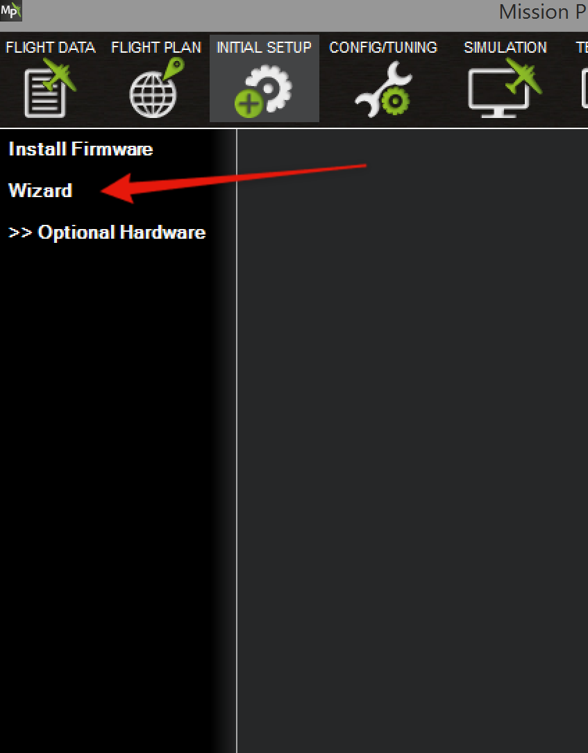
Now you will want to go to Initial Setup at the top:
And then to wizard:
There will also be an option to manually calibrate each part. I personally used the manual calibration. You can find this under the Mandatory Hardware section (which will show up above the Optional Hardware section). From here, you will basically do what the wizard takes you through, just on your own. I suggest that you stick with the wizard, as it is the simplest way of doing so. If you would still like to do it manually, here is a great YouTube video I used to help guide me through that process.
As you walk through the wizard, it will ask you to do compass calibration. APM 2.6 has moved the compass outside of the unit so that it can be mounted away from electronics to prevent interference. Though this makes sense, I haven't encountered any interference on my compass even when running all motors at full power. Regardless, to do this, you will need to connect your uBlox GPS to your APM. This can easily be done by wiring the GPS port the the GPS on the APM, and the MAG port on the GPS to the I2C port on your APM. When doing the calibration, you will need to gather test points for your compass. Rotate your compass around and save data waypoints as you go. This will likely take some time to do right. I saved over 2000 data points to make sure it was perfectly calibrated.
RC Setup
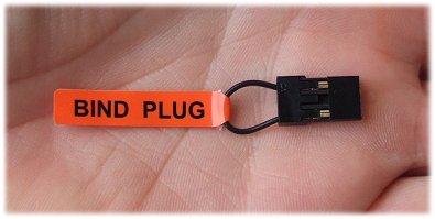
As you are walking through the wizard, you will get to the RC calibration section. Before you can do this part, you will need to first bind your RC transmitter (controller) to your receiver. This is typically done using a bind plug which comes with your controller.
Source: rc-airplane-world.com
You will connect this bind plug to the first port of your RC transmitter. If you did not receive a bind plug, you can make your own! It is actually quite simple. All you have to do is take one of servo extension cables and short the signal and ground. How I did this was I took my wire cutters, cut off one end of the servo connector, and stripped it. I then used pliers to pull out the middle pin, and soldered the signal and ground cables.
From there, you simply have to connect any input to your APM inputs using a Female-to-female servo connector, and the transmitter will get power. It will not light up, but assuming you have aligned up the wire correctly into the input, it will get power. To confirm you have done it right, make sure your signal lines go to the signal line on the APM, the power goes to power, and the ground goes to ground. Power and ground areusually indicated on your connector by red and black cables respectively. This is the power circuit in the APM taken directly from their website.
Now, just hold the bind button on your transmitter (controller) and power it on while still holding bind. Make sure your throttle is all the way done as you power it on. It should beep a few times and the receiver light should turn on. This means that the transmitter has bound to the controller successfully. What this means is that the controller is now always paired with only this transmitter (unless you reset it with the bind button). This is to prevent others from accidentally sending information to your transmitter, and to prevent you from accidentally sending data to someone else's receiver. In a way, it is similar to how you pair a smartphone to a bluetooth device. You are essentially pseudo-permanently pairing your transmitter to your receiver.
If this doesn't work the first time, no worries! Make sure you have connected your receiver to the APM correctly, and make sure the APM is getting power (either through the computer or though battery). Try again a few times. If it doesn't work, I'd suggest looking up your manufacturer's instructions for binding. From the research I've done, it is pretty standard all across, but I haven't tested multiple transmitter/receivers to confirm that.
We now have to wire the transmitter fully to our APM. This can be done by following this easy-to-use diagram:
Match the pin-outs of your transmitter with these inputs on your APM. An issue I seemed to read about often in my research is that people will often miswire throttle, because in a lot of receivers, throttle is channel 1, while in the APM it is channel 3. Make sure to confirm with your receiver's manual/guide as to which pin is which. Just use your Female-to-female servo connectors to connect them, and you should be all set!
Now moving back to the APM wizard, you can calibrate your RC controller by confirming you are in calibration mode on Mission Planner and then moving all your RC sticks in to all edges and all possible directions. The page should look something like this, as seen on APM's website:
Once done, you can now set up flight modes for your RC controller. This is where APM really shines. Since APM is such a mature set of technology, they have really refined their algorithms quite a bit. Because of this, they are able to provide you with flight modes like Stabilize, Loiter, Return to Home (or RTL), Acro, and so on. The major ones to know are Stabilize, Return to Home, and Acro. Stabilize does exactly what you probably think it does. It will follow your manual controls, but attempt to stabilize itself as you are flying. I highly recommend this for any beginner, and you will be surprised at how hard it is to fly on your first flight. After a while, it will seem easy because you have done it before, but in the beginning, it is daunting and you are scared of crashing. Think of it like learning to drive a car! If you have driven for a while, driving becomes extremely easy! You don't even think about it. However, if you think back to when you were learning, I am sure you can recall the little apprehension you had, mixed with excitement, as you sat in the driver's seat for the first time. Return to home will simply attempt to come back to take-off position and auto-land. This is a very useful feature, but it is dependent on your calibration. The more accurately you calibrate, the better/more successful this feature will be. I found it difficult to perfectly calibrate it myself, so I found the full tree parameter list, and manually offset some values to my liking. Finally, there is Acro mode which is basically free mode with the APM that just follows exactly what you say. This is the true manual control. This will be hard to use! However, it is a great debugging tool to see exactly which offsets are wrong.
One mistake I ran into when manually setting my offsets was that I was adjusting based on how the flight acted in stabilize. Because of this, I wasn't getting great results. Once switching to Acro mode, I was able to more accurately set my manual offsets, providing for better flight.
You will be able to set your modes through the flight-mode section of the manual mandatory hardware configuration. As you move your switches around on your RC transmitter, different sections will highlight, telling you what each switch position means. From there, you can change those decisions accordingly. I personally recommend using Stabilize as a learning tool, Return to Home to help you land, and Acro to debug and see why something isn't acting correctly.
Finally, there are the fail-safe modes. This is what will happen when your battery voltage drops too low, if your RC transmitter (controller) dies, or if you start flying our of range of your controller. I suggest setting this to Land or Return to Home so that if anything like that goes wrong, you are safe, and your drone won't fly away. You might think that is ridiculous, but that is a surprisingly huge problem in the industry--even for commercially made drones! In fact, it is so common, that the Wall Street Journal wrote about it.
Motor to ESC Connection
Before we can connect the electronic speed control (ESC) to the motor, we need to connect the motors to the their respective mounts.
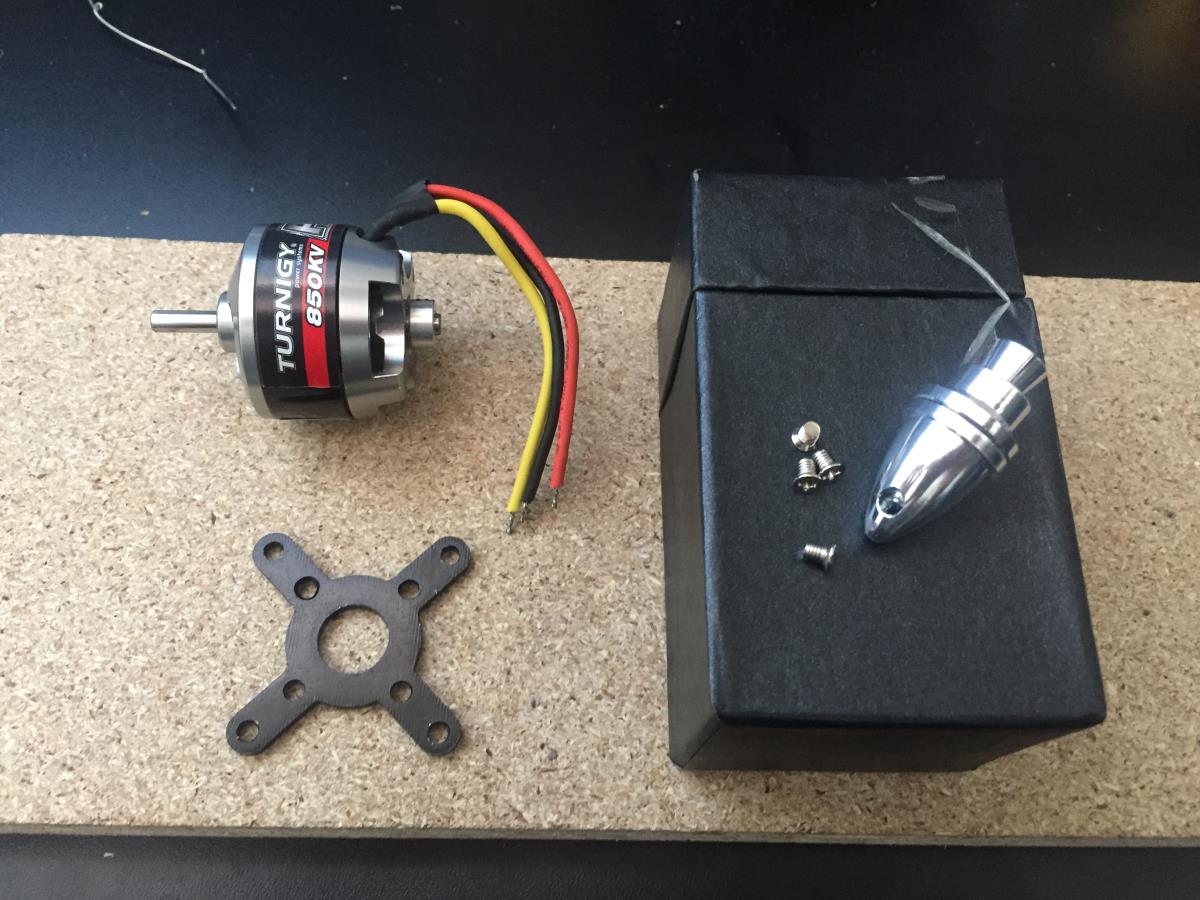
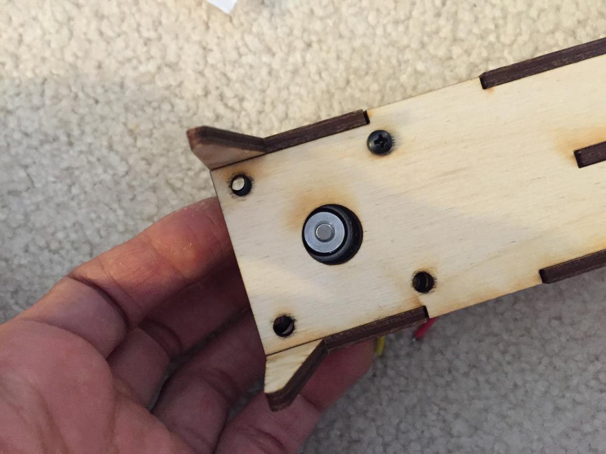
The first step is to take out all the parts and make sure you have the motor, the mount, four motor mount screws, and a propeller adapter.
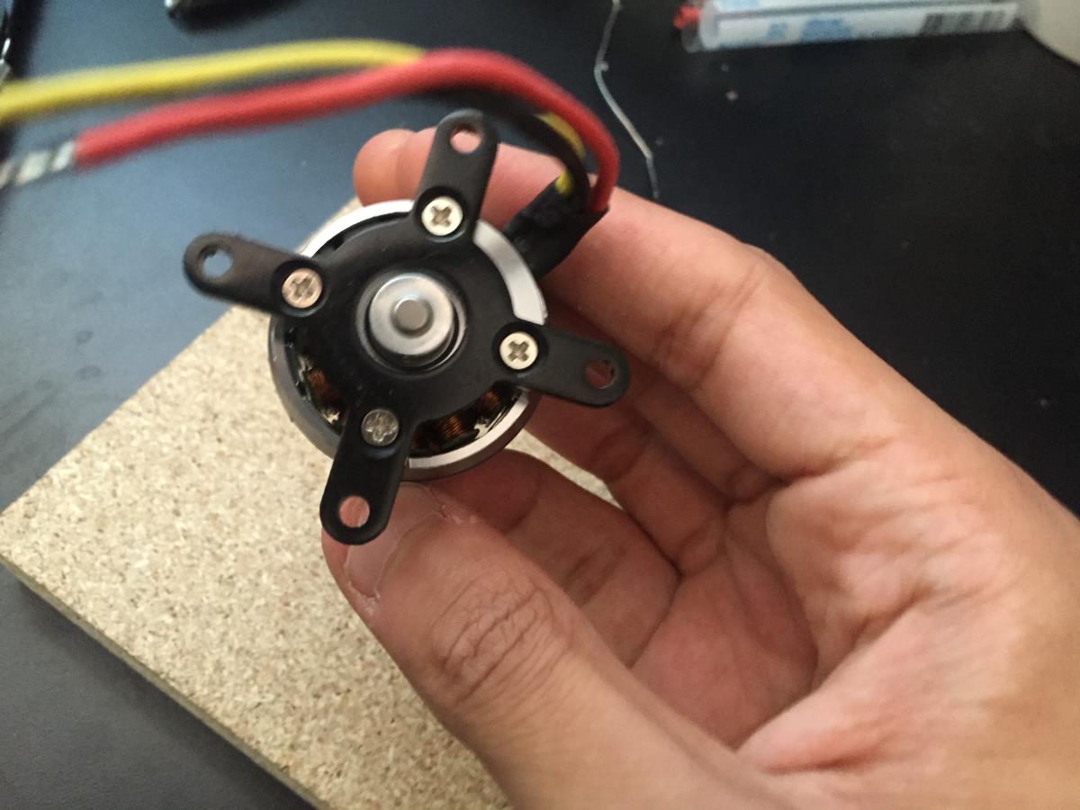
Next, align the motor mount to the motor. You will want to keep the side with the holes curving inwards on the bottom.
Then, simply use the provided motor mount screws to connect the motor to the motor mount. Be sure to make these tight as once you mount this onto the frame, they will be difficult to access. You will do these for all four motors.
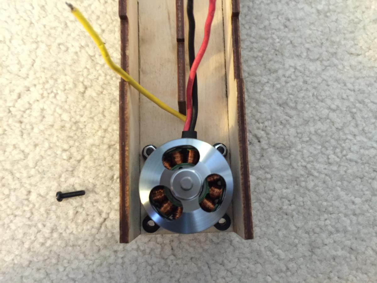
Once you have connected the motor mounts to each motor, you have to connect the motor to the frame. One of the mistakes I made was setting up my motors with my ESCs before mounting it onto the frame. After setting everything up, I came to realize that simply cannot fit the motor to ESC wires through their intended slots without undoing them. The following shows the mistake I made. Similarly to my mistake in frame assembly, you should not do any of these steps. These is merely to show the mistake I made so you do not repeat it.
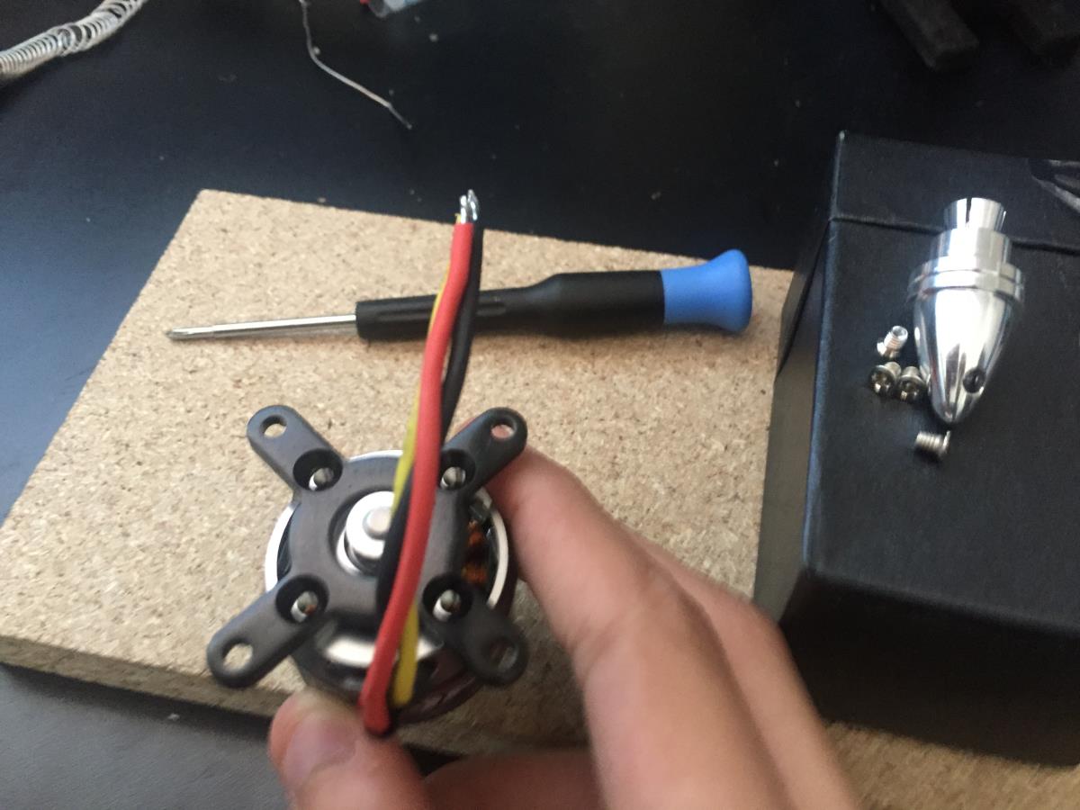
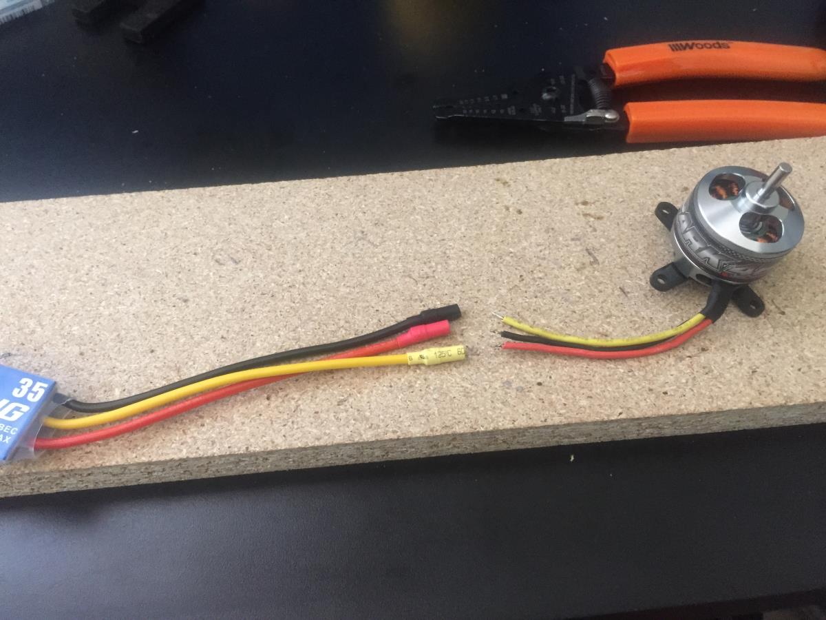
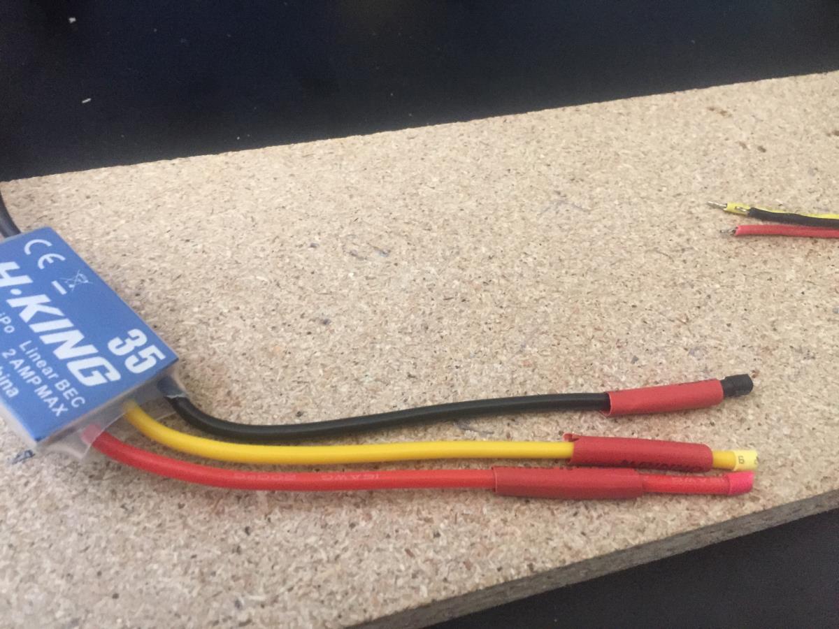
If you take the motors and the ESCs, you will realize that the ESCs come with bullet connectors while the motors just come with exposed stranded wire.
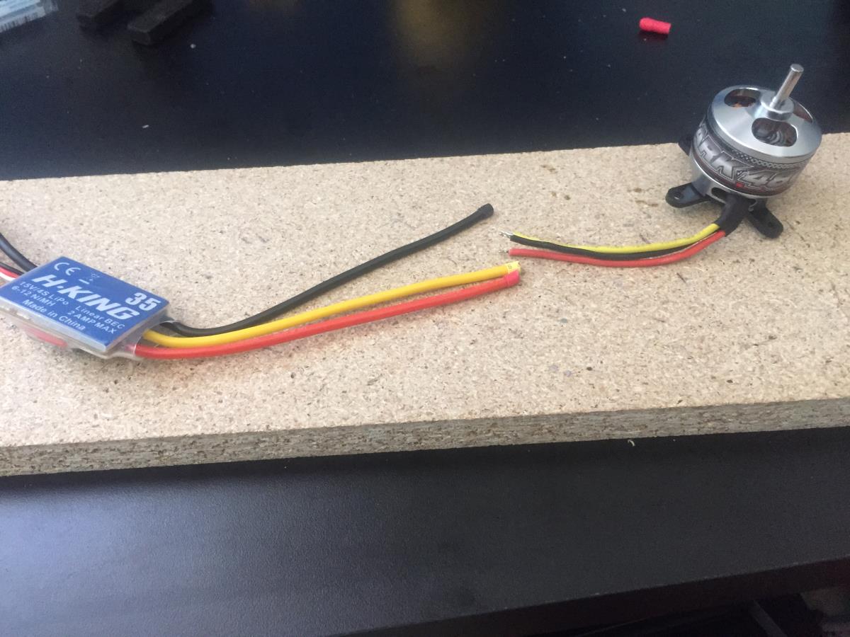
One option you have is crimping and connecting bullet connectors to your motors. However, I chose the route of soldering them directly on as this not only provides a more solid connection between the motor and the ESC, but it also was easier for me to just solder them. To do this, first you have to use your wire cutters to cut off the bullet connectors on the ESCs.
Next, you need to cut a piece of the 5mm heat shrink off and put them over the ESC wires. I used about an inch of heat shrink for each wire. Make sure not to forget this step before soldering, as you will have to de-solder the wires and put on the heat shrink.
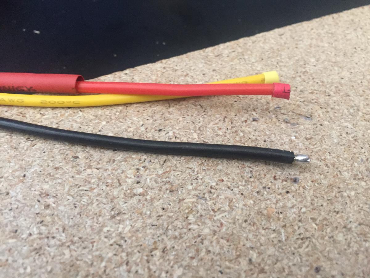
Then, use your wire stripper to strip off a small section of one wire on the ESC. I started with the ground wire (marked as black).
Now, simply tin each wire a little bit, and solder the two pieces together. Slide the heat shrink over the solder connection and then lightly apply your iron on the heat shrink to shrink it and insulate the solder connection. You can also use a lighter for this as it may be quicker, but I found it easier to just use my soldering iron.
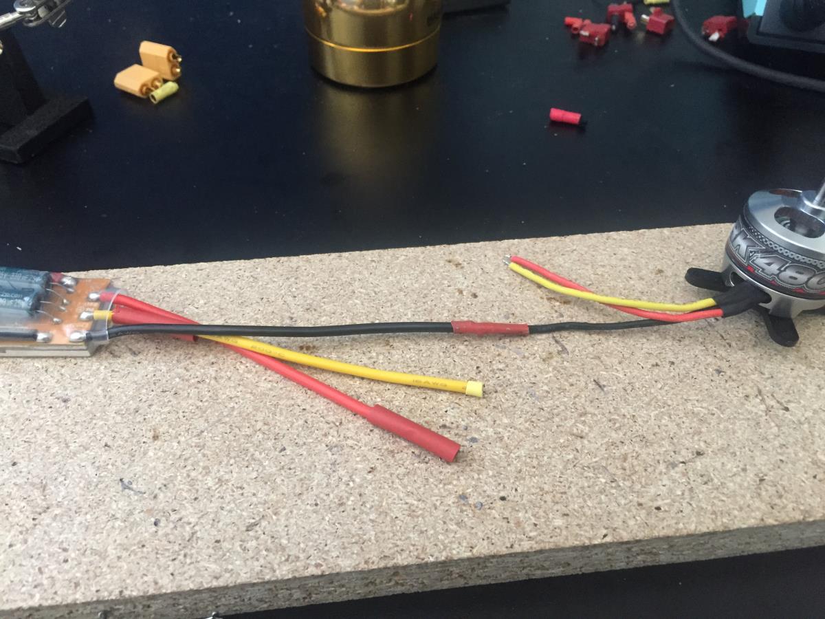
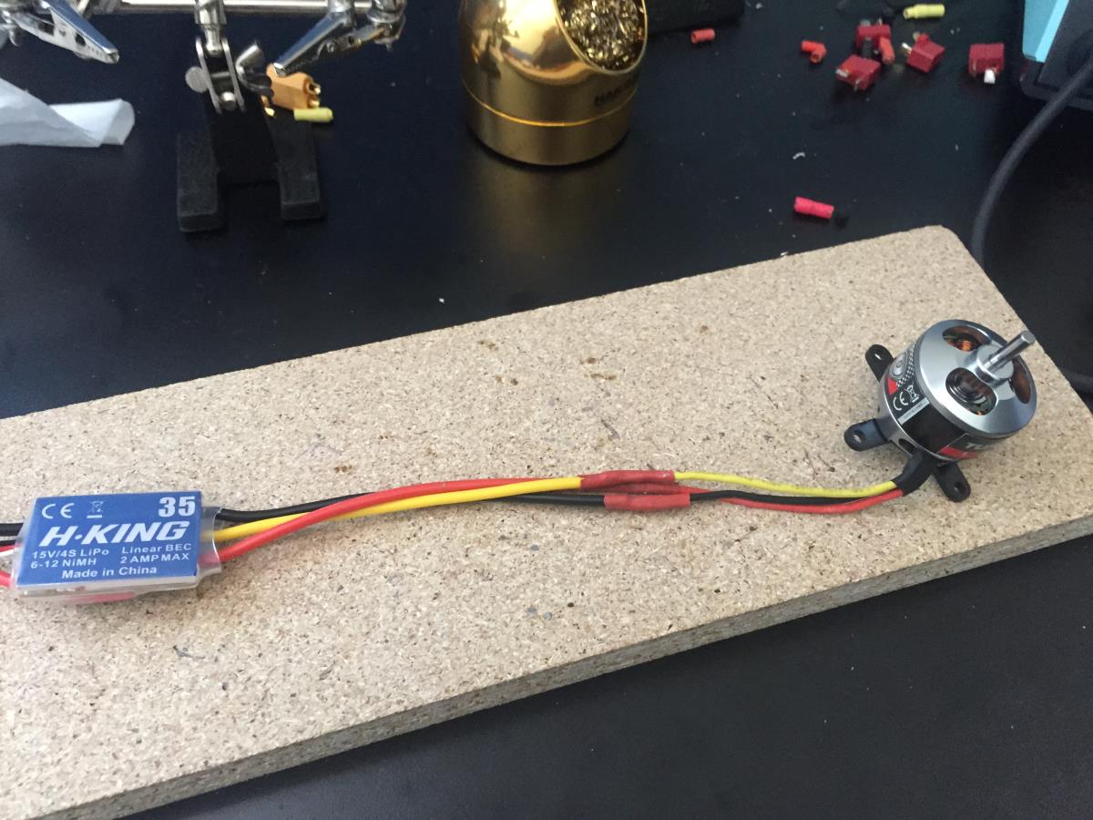
Now, repeat these steps with each wire. To prevent any accidental shorting, I did each wire at a time. The wires should be color coded, so soldering them together should be straightforward. Just match the black with black (ground), the red with red (power), and the yellow with yellow (signal). In the end, you should have a fully connected motor and ESC combo.
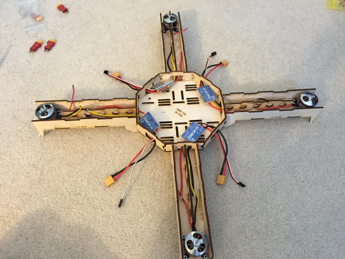
Repeat these steps for all four motors, testing each one as you go. This is where I made the mistake. All of these steps are correct, except that since the wires are now soldered on, you won’t be able to fit them into the ESC/motor holes on the opening of each arm in the frame. When you go about doing this, first align the mounted motor to the arm as so:
Now simply take your M3 screws, washers, and nuts and mount them to the arm. I found it much easier to do the screws closest to the center first, and only after doing the outer ones.
Do this for all four motors. Now you should wire the ESCs through their respect holes so each motor has an ESC:
Now following the steps above, solder the connections. The ESCs should fit in the center, and the wires should all be soldered:
Again, check that each motor runs using the battery. Along with this, you should calibrate each ESC with your RC transmitter. To do this, you connect your ESCs to the battery, and the 3 pin servo connection to the throttle pins on your RC receiver. From there, you have to calibrate your ESCs individually using the APM manufacturer's instructions:
Plug one of your ESC three-wire cables into the throttle channel of the RC receiver. (This is usually channel 3.)
Turn on the transmitter and set throttle stick to maximum (full up).
Connect the LiPo battery
You will hear a musical tone then two beeps.
After the two beeps, lower the throttle stick to full down.
You will then hear a number of beeps (one for each battery cell you’re using) and finally a single long beep indicating the end points have been set and the ESC is calibrated.
Disconnect battery. Repeat these steps for all ESCs.
If it appears that the ESC’s did not calibrate then the throttle channel on the transmitter might need to be reversed.
If you are still having trouble after trying these methods (for example, ESCs still beep continuously) try lowering your throttle trim 50%.
You can also try powering your APM board via the USB first to boot it up before plugging in the LiPo.
You need to do this because though you calibrated your RC controller on the APM, your ESC does not know your throttle ranges. This calibration will teach your ESC what the minimum and maximum values for your throttle are. You may also attempt to do the All-at-once calibration, but that did not seem to work for me and I do not believe the ESCs I use are compatibile with that. You can find that information, as well as the source for the steps above here. To check if your ESC is successfully calibrated, try controlling your motor with the throttle and make sure that the motor is responsive as soon as you move it. If the motor does not respond to lower throttle values, but then immediately picks up at a certain point, it is likely you haven’t correctly calibrated your ESC. If it still doesn’t work, it is possible that you are moved some of the switches that artificially increases your throttle minimum and maximums.
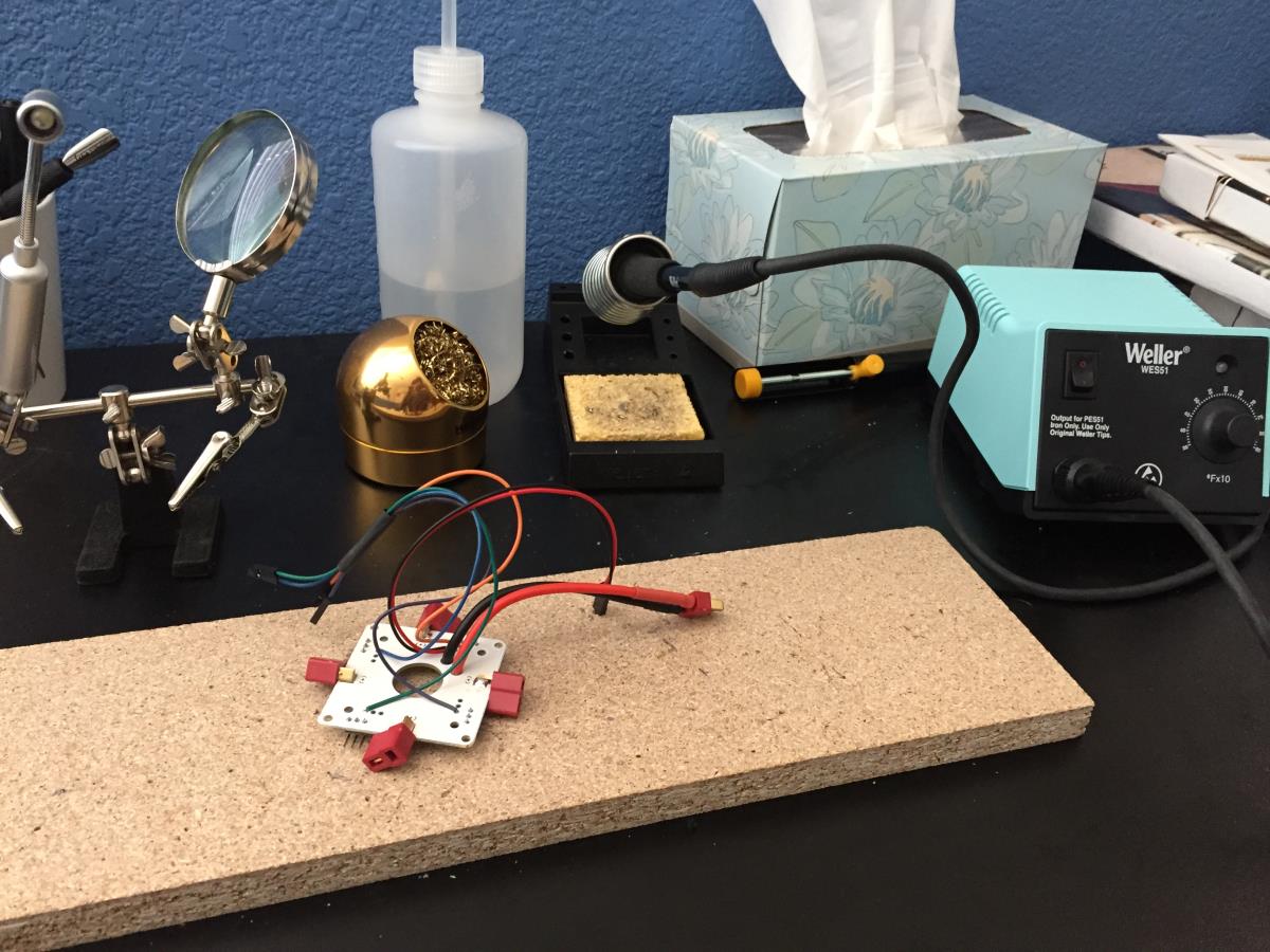
Power Distribution Board
Now, let’s move on to the power distribution board. Up until now, we have connected the battery directly to the ESC to power the motor. When we fly, however, we need to power all four motors at once! To do this, we need a power distribution board. These are relatively simple, and you can buy or make your own using perfboard. To make your own, you just make rails for power and ground, make sure they aren’t shorted, and connect an input adapter to each, and four output adapters. I planned to do this, but ended up doing a mix of buying and building one. My initial plan was to buy one as they are pretty cheap, and test out using it. After that I would build my own. However, I realized that the one I bought was pretty useless to me as the adapters were different. Only the input matched my battery.
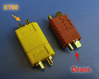
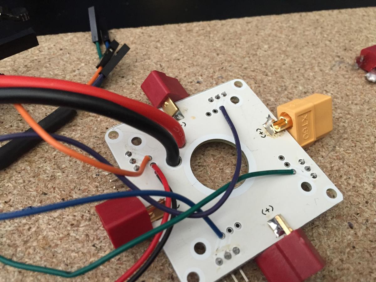
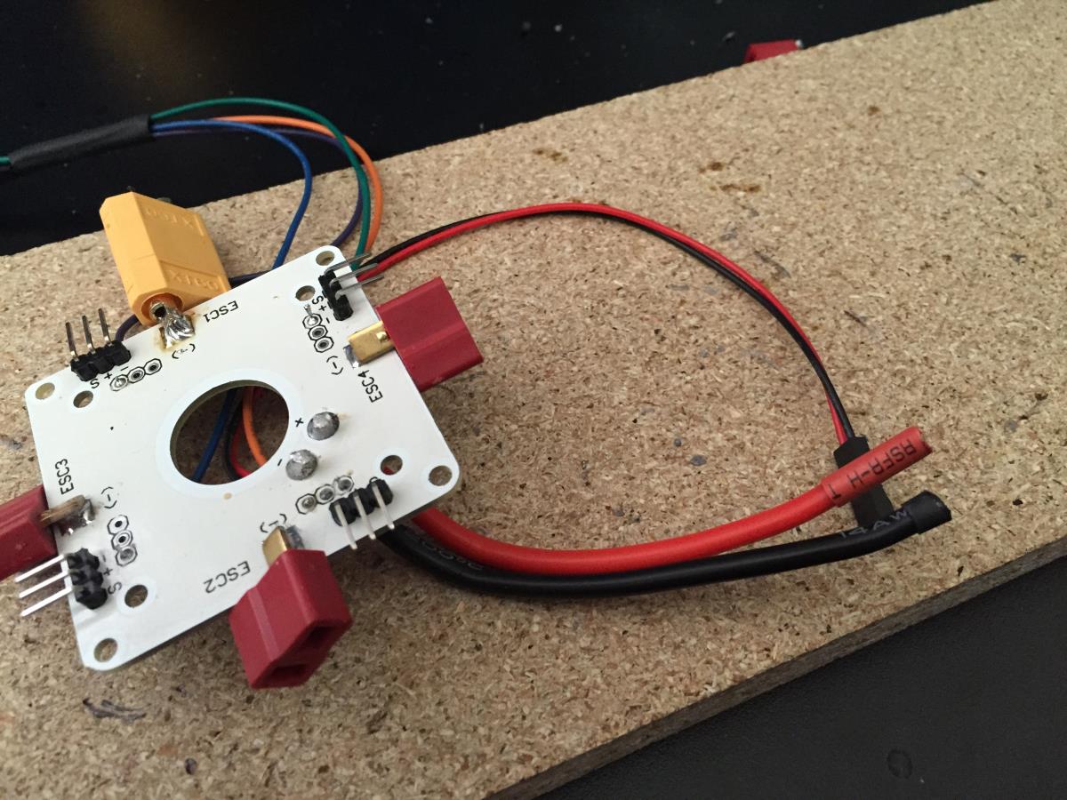
Since I am new to this, I did not realize how many different plugs and adapters there are for these parts. Instead of searching for various adapters for all the parts, I found it to be much more efficient to simply cut off all the connectors and solder on new connectors. I used the XT60 connectors as they seemed to have the most protected and solid connection compared to the other connectors offered, like Dean’s (or T Plug) connectors.
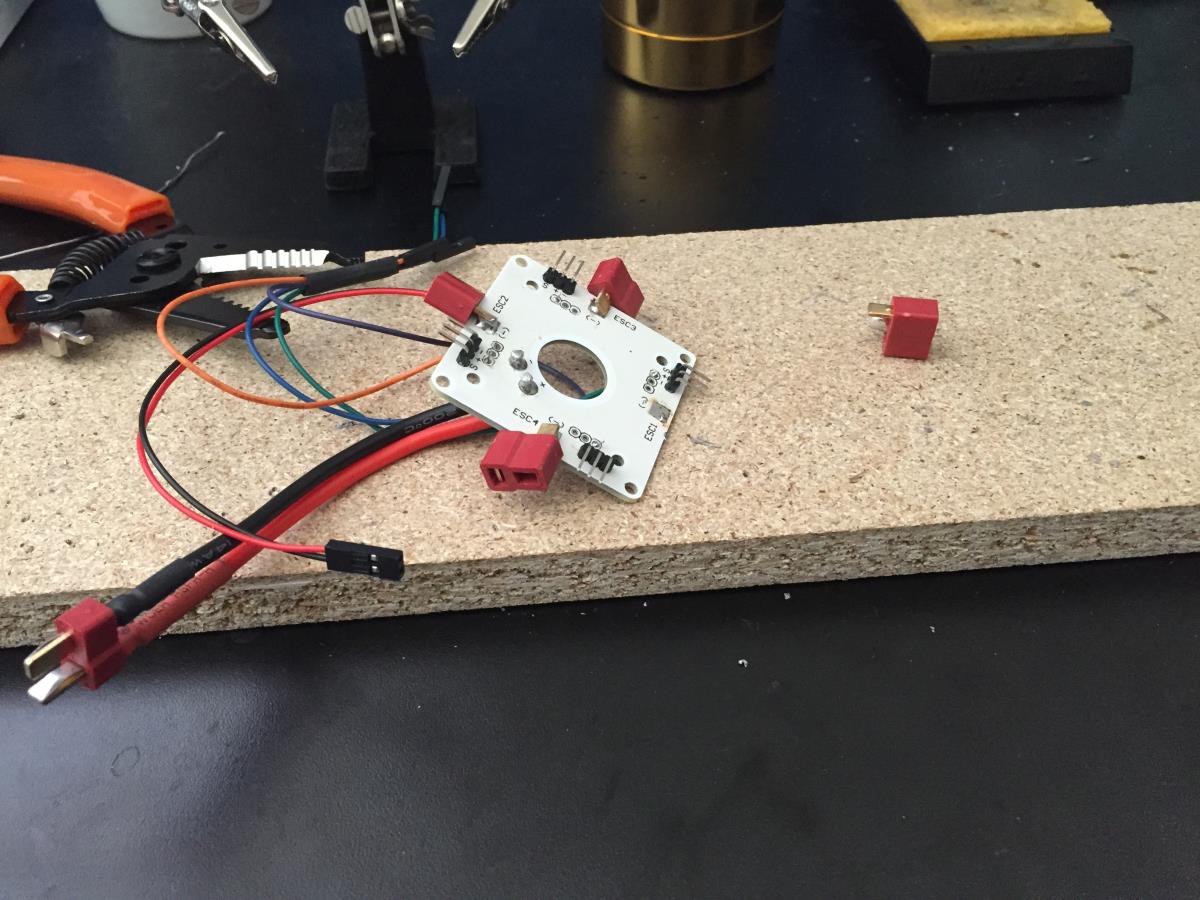
So what I did was basically I started by de-soldering one of the adapters on the power distribution board (PDB).
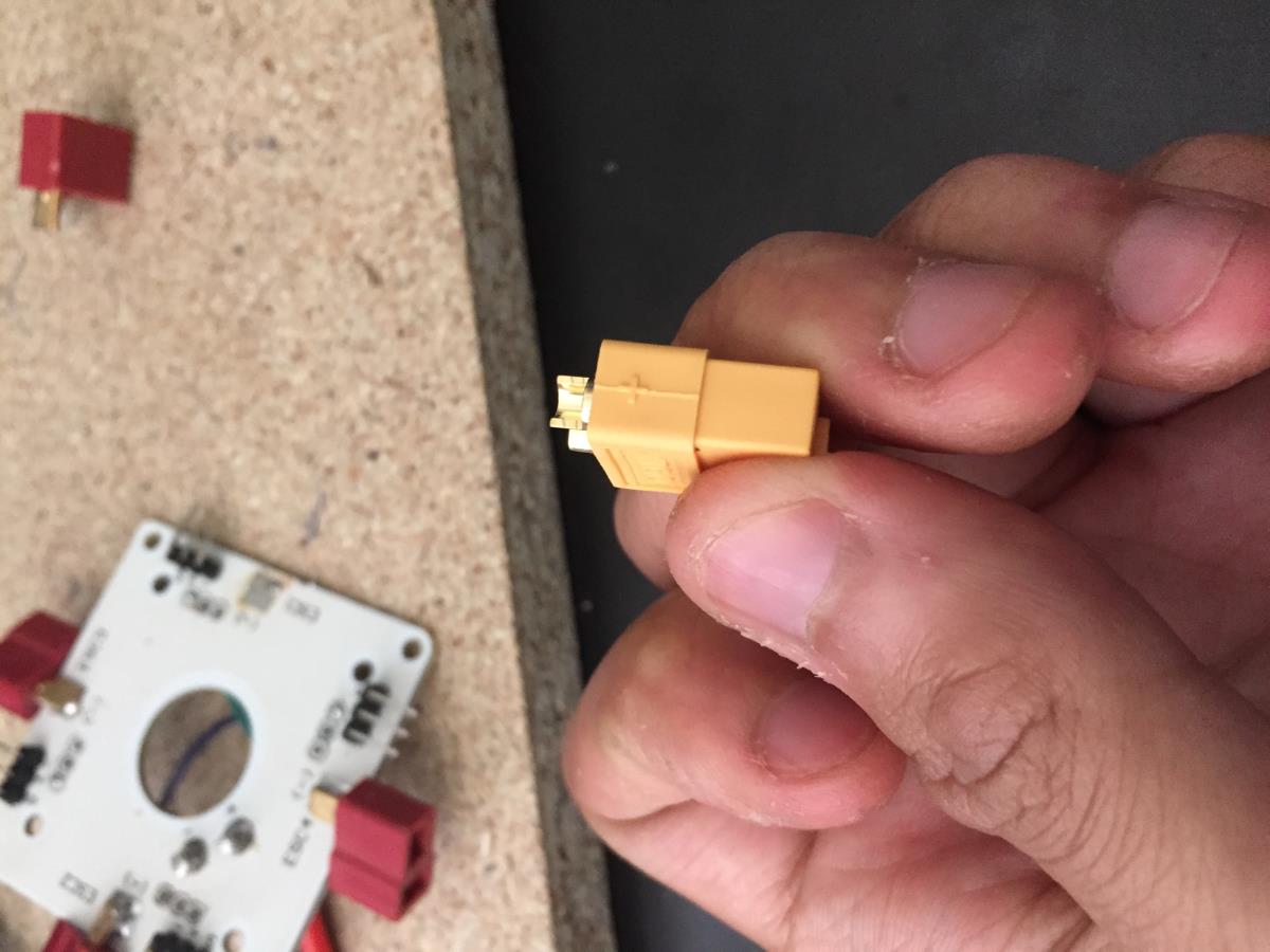
Then take an XT60 adapter and make sure to align the positive side with the power rail pad
And solder the power side on:
Make sure the adapter is aligned, and solder the other side (negative side) to the ground pad
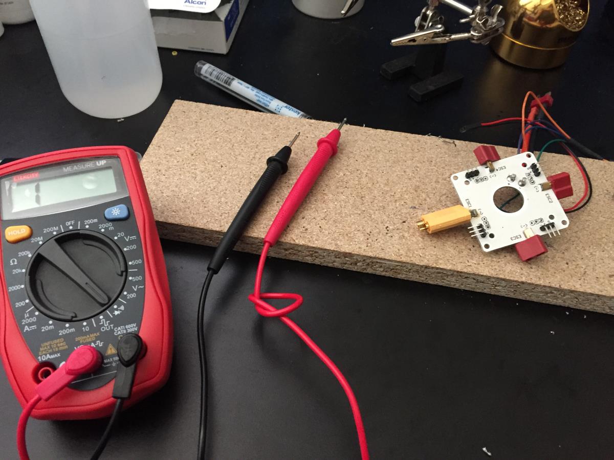
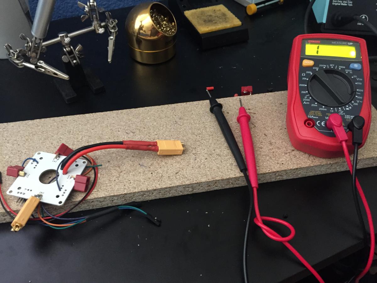
Check that you don’t have any shorts with the continuity mode on your multimeter.
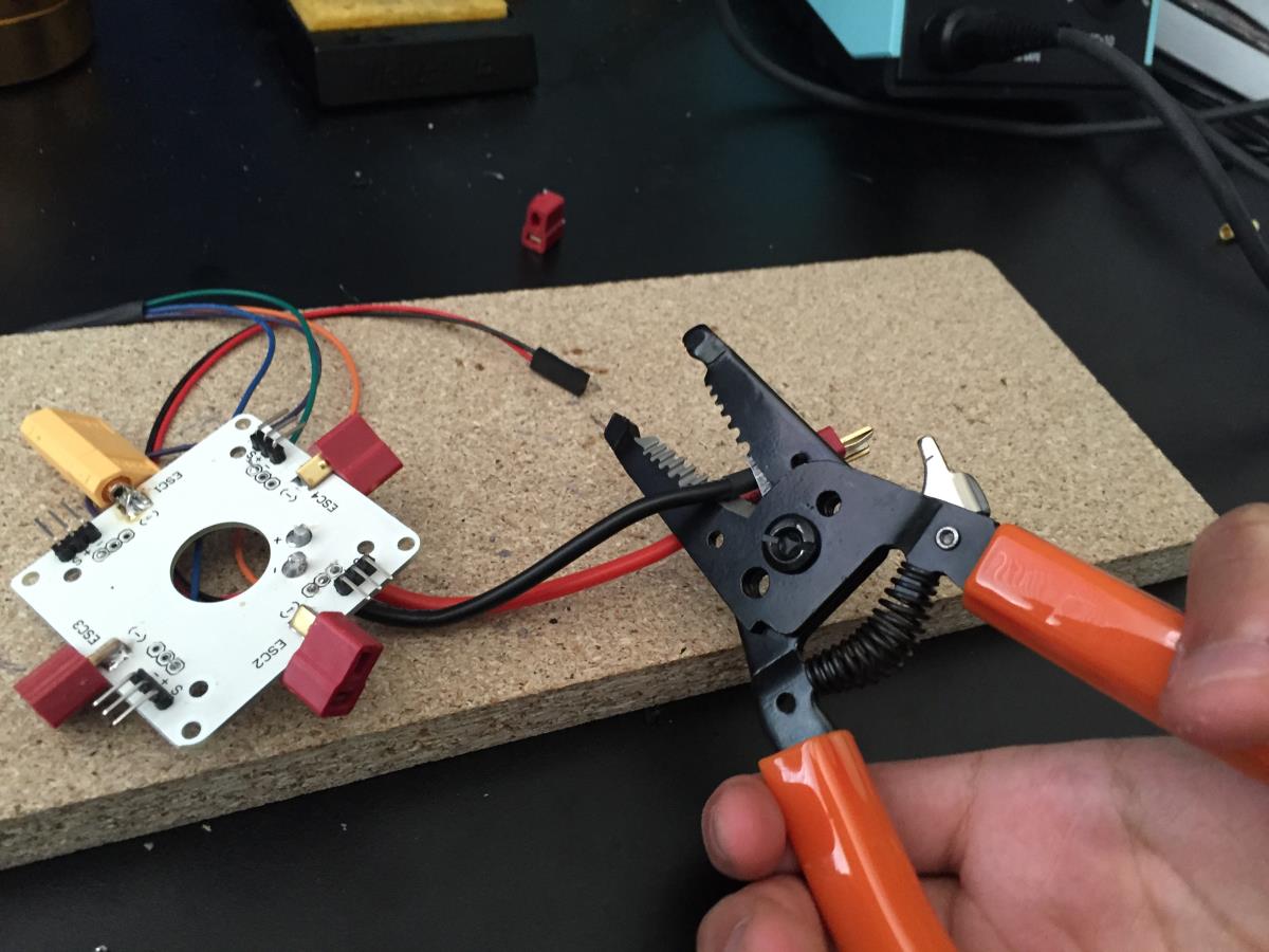
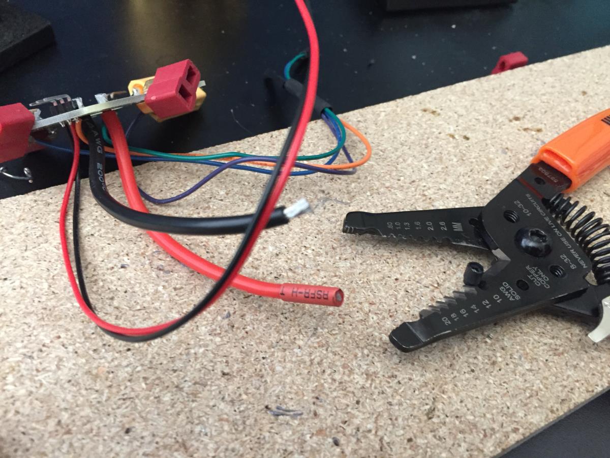
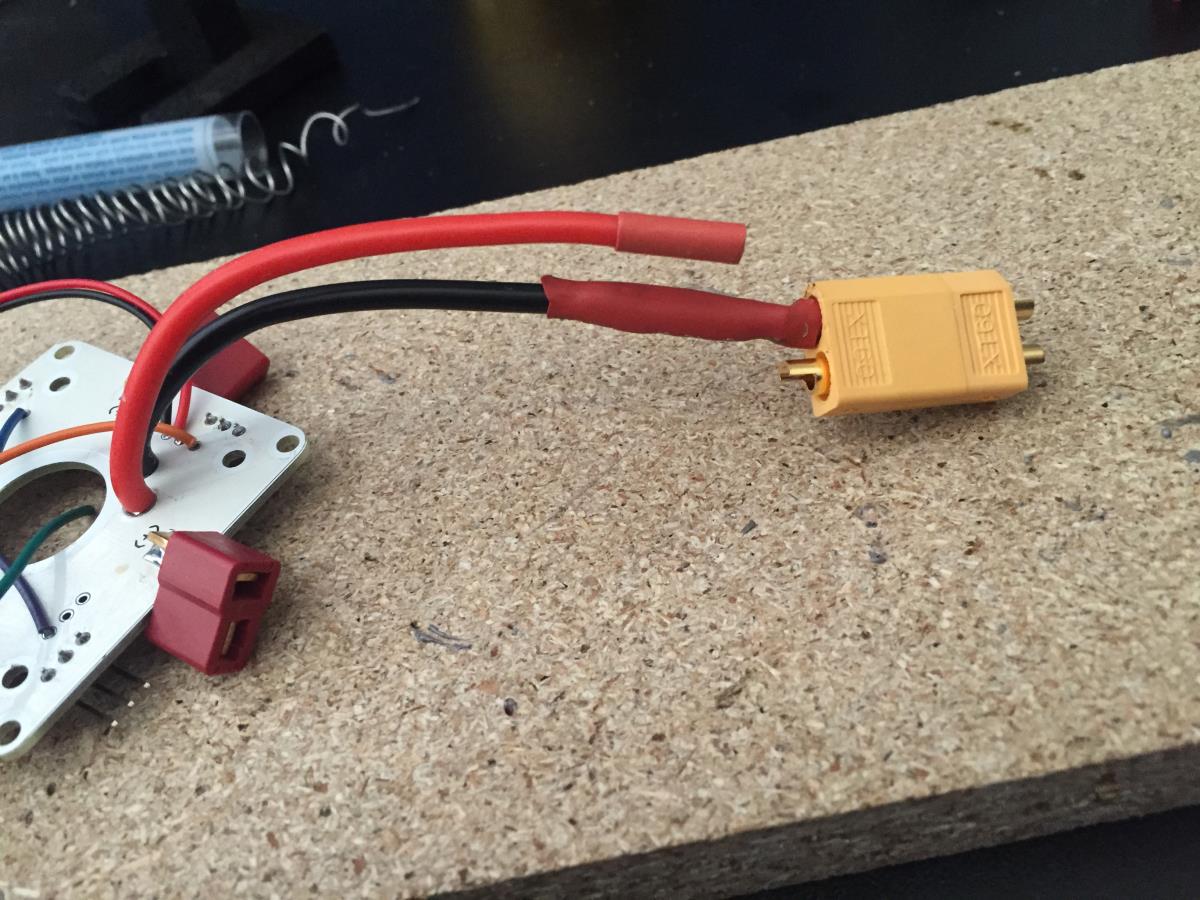
Cut off the power input adapters as well, so you can put on the XT60s. You may be wondering why I am doing this if they are both Dean’s (T Plug) connectors, but unfortunately, they are both male, so you are going to replace it, regardless. I prefer to stick with consistency, so I soldered a XT60 adapter on.
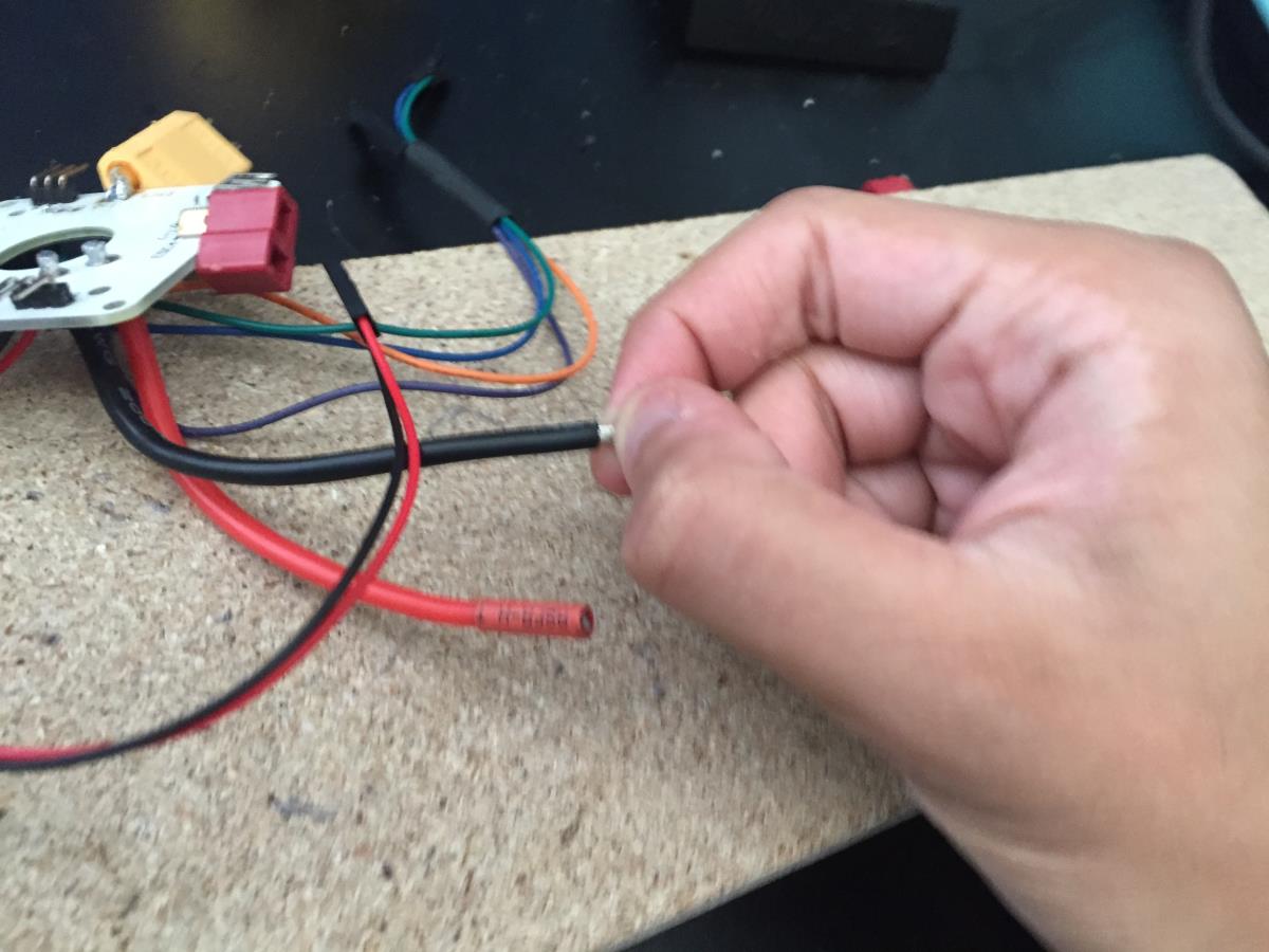
A tip to solder such low gauge stranded wire is to first strip a little
Twist the strands in a counter-clockwise direction
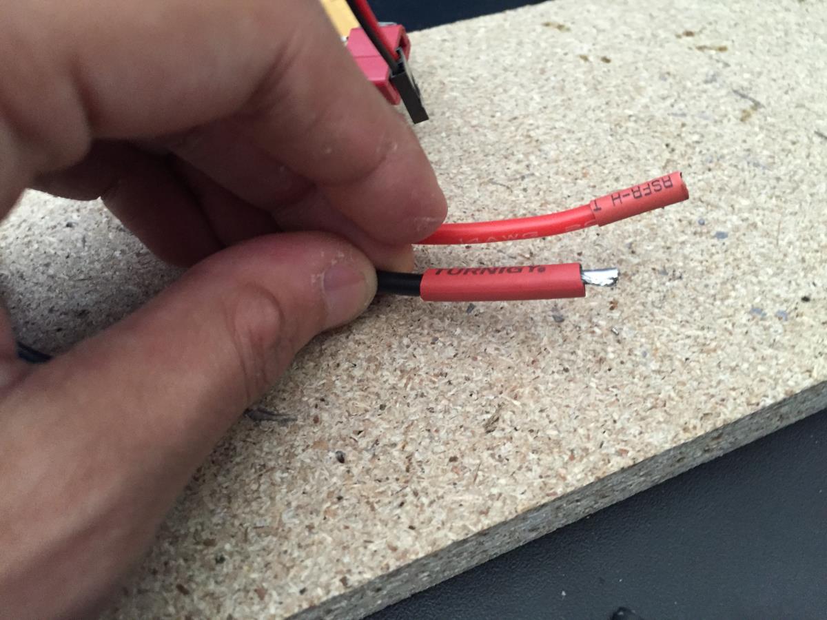
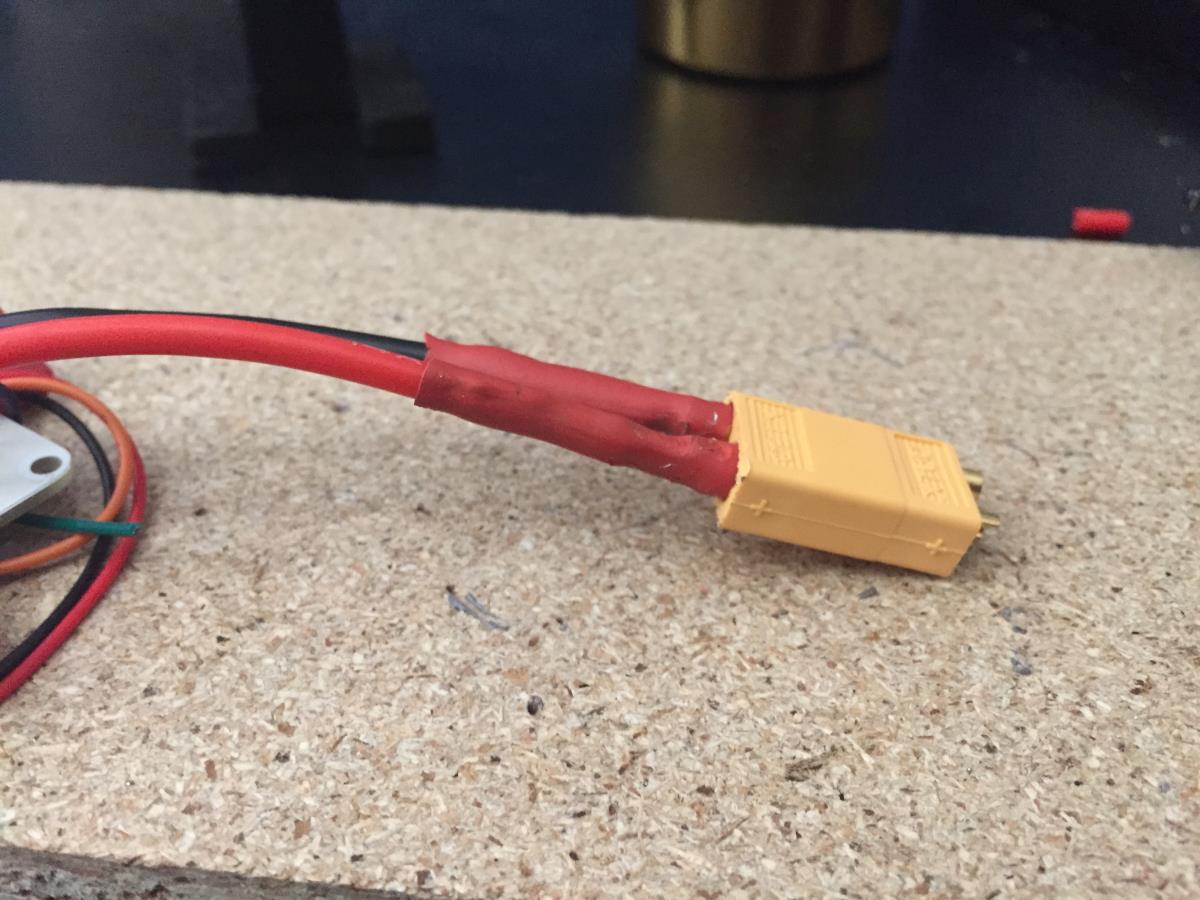
And then tin it with a little solder. Slide some heat shrink on it
and solder the ground to the negative terminal on the XT60 adapter.
Repeat these steps for the power cable as well.
Check that you haven’t shorted anything with your multimeter in continuity mode.
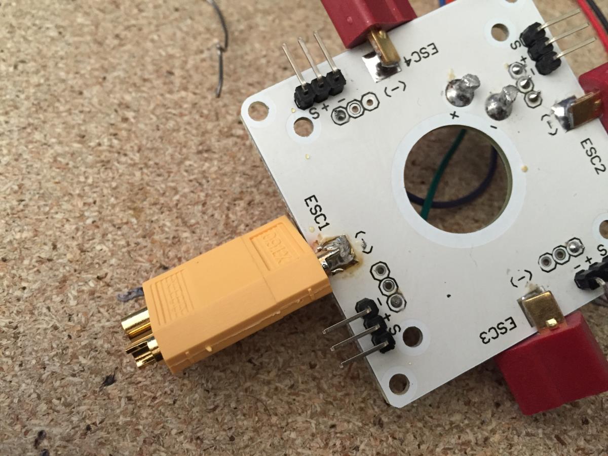
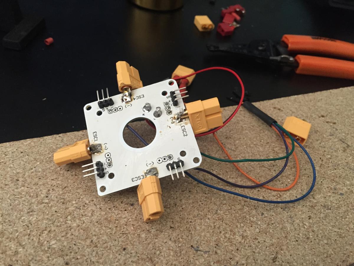
Now go back to the PDB, de-solder the other Dean’s plugs, and soldering on the XT60 adapters. Make sure to keep the positive leads of the adapters on the power pads, and the negative leads on the adapter on the ground pads.
Again, check for shorts all the way around using the continuity check on your multimeter.
Now you are going to want to connect all your ESCs with motors to the PDB, and connect the battery. Use your APM power module to connect to the PM port on your APM, so that the battery will be able to power not only the PDB, but also your APM.
Note that this image also shows my mistake earlier with connecting the motors without first mounting them onto the frame.
Test each motor with the PDB to make sure it works!
Charging the LiPo
This may seem like a simple concept. But for someone who hasn’t done this before, there are certain aspects you need to know about charging your LiPo. Typically, LiPo chargers come in the form a four button charger. This charger can typically be used to charge many types of batteries. For our purposes, we will stick with the LiPo functions:
LiPo Charge
LiPo Fast Charge
LiPo Storage
LiPo Balance
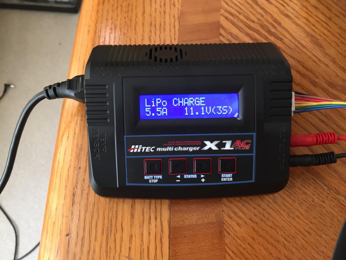
LiPo charge is pretty straight forward. You have to set up your settings to match your battery. Simply put the mAh to amps on the charger (5500mAh = 5.5A). Then set up the cell number/voltage of the battery. My battery is 3 cells so 3S or 11.1V. Then simply hold down the start button, it will run a battery check, and then begin charging. One way to know that you are fully charged is that either your LiPo will stop charging on its own, or the battery will reach 12.6V, which is the max charge point for a 3S battery.
LiPo fast charge is also just as the name says. It charges the battery quicker, however, it decreases the battery life. I would recommend not using this, and just stick with LiPo charge, as it should charge the battery in about an hour.
LiPo storage mode lowers the power on the LiPo battery to keep it in optimal situations for storage. Since LiPo batteries have the special property of requiring a charge even when not in use, LiPo storage sets the power to the optimal value needed to maximum battery storage. This is also how your battery will come shipped as—so you will want to charge it when you want to use it.
LiPo balance mode equalizes the charge in all the cells of the battery. The battery I bought has 3 cells so using this mode, I can balance the cells to have equal voltage, providing the best results from the battery. At full charge, each cell should have 4.2V.
Assembling the Anti-Vibration Mount
Before we can mount all the electronics onto the frame, we will want to set up our anti-vibration mount. The anti-vibration mount helps keep the APM from moving too much. Since the APM houses the accelerometer and gyroscope, it is important that it is kept as level as possible. With four brushless motors running, the frame provides a decent amount of vibration. With these anti-vibration mounts, we can minimize that vibration while still letting the APM modules react to flight changes.
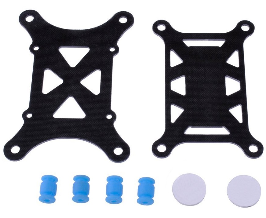
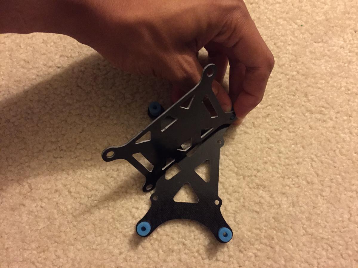
Unfortunately, assembling this is quite a pain! When you receive it, it is given to you in parts. You get:
Base Layer
Top Layer
Flexible Rubber Spacer (x4)
3M Circle Command Stick (x2)
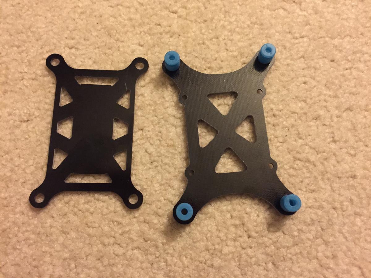
To assemble this, you have to squeeze the rubber spacers into the holes on the APM. This is actually quite difficult, and I would recommend using tweezers or a small blunt part of a pen to help fit the spaces in the holes.
I started by attaching the spacers to the base layer:
From there, slowly attach the spacers to the top layer, being careful not to squeeze too much as this can break the spacer.
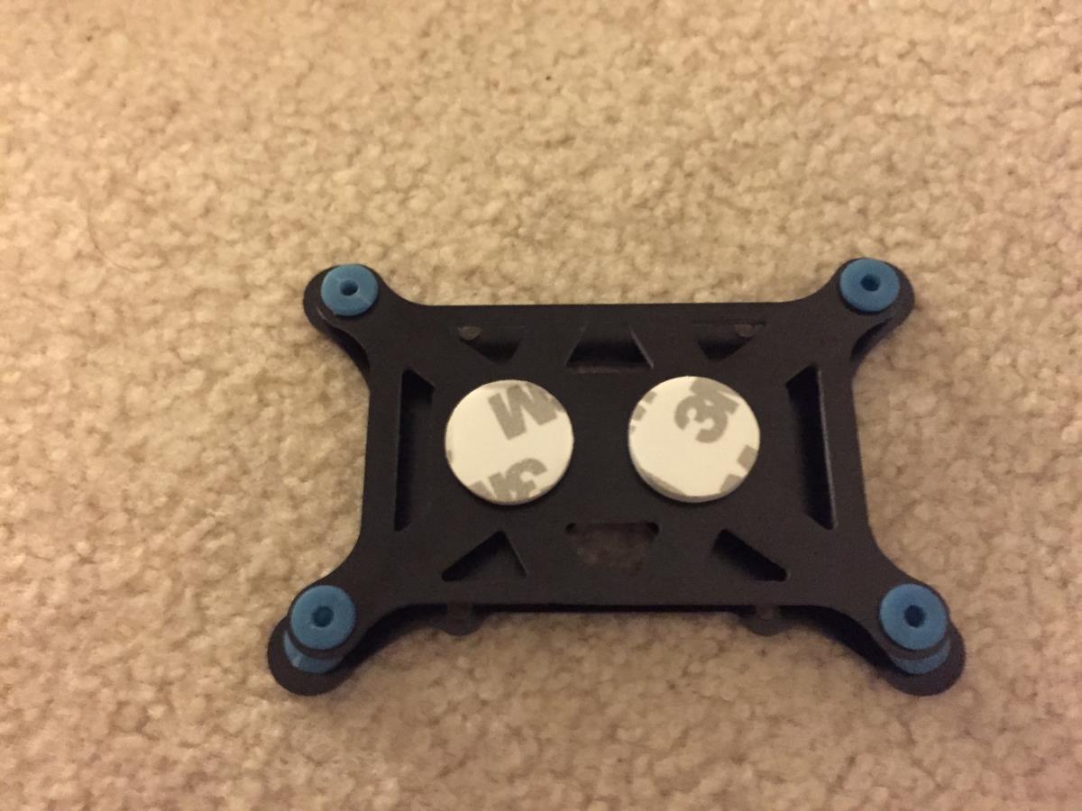
Once all are attached, simply stick the APM to the mount using the 3M adhesive provided. I would suggest first attaching the adhesive to the mount first instead of the APM, as the APM has a flat bottom, while the mount has holes. Also, this allows you to center the mount to come out like this:
Fitting Electronics into Frame
The parts are finally ready to mount onto the frame! Now fitting all the parts into such a small space in the center console is actually quite the challenge! The most important part of all of this is make sure you do not cover the four main screw holes that got through each layer to ultimately hold them together. So when placing everything together, make sure all these holes align.
Ideally, I wanted these holes to automatically align if you made sure all the text was facing the same way. Unfortunately, I misjusdged the alignment of the top layer in comparison to the middle and bottom layers, and thus, I need to manually make sure the holes align. I have, however, adjusting my laser cutting files, so if you were to use them now, you will not have this problem and you can just align the text.
Another concept to keep in mind as you try placing the electronics on the frame is that you should try and keep the GPS unit as far away from the ESCs and PDB as you can. I have read many reports of people have issues with having their GPS near their ESC/PDB. This is due to the fact that since there is so much current passing through the PDB and ESC, it can cause some magnetic interference with the external compass on the GPS unit. This was actually the reason why APM decided to remove their compass from being in-built, like they have in APM 2.5, and now ask for an external compass.
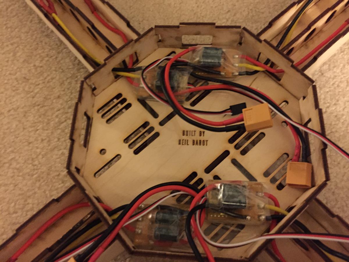
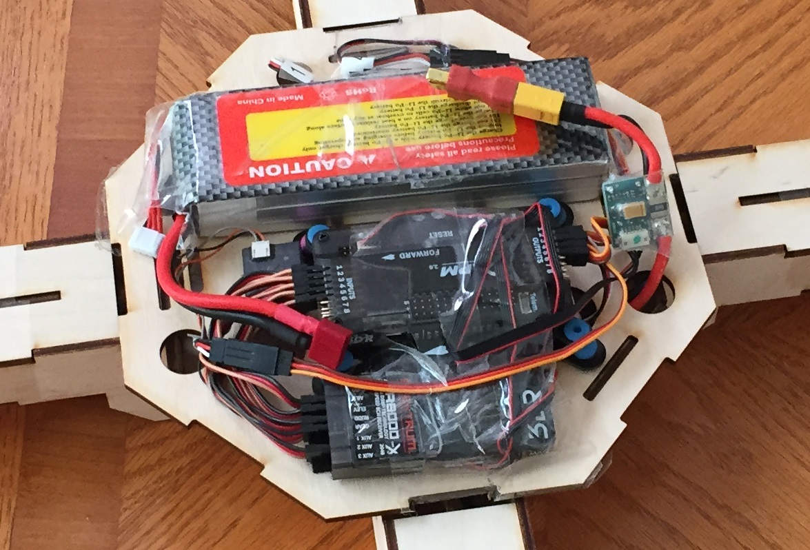
For me, the best arrangement that worked was having the ESCs and the PDB on the absolutely bottom layer, with their relevant wires sticking through the middle layer holes as follows:
and then to have the rest of the components on the top layer.
In this picture, you may notice that I simply used tape instead of zip ties. The reason for this was because of the fact that I had issues with counterfeit parts, I chose to use tape to secure everything down in case I'd need to replace anything else. Once you find a working arrangement, I suggest you secure it more semi-permanently, like with zip ties. And the last but one of the most important aspects to remember, is to make sure that your APM's front is facing the front of quadcopter. This should also match the front on your GPS module. Both will have a front arrow to guide you. I used a set square again to help me get this right.
Motor Rotation Calibration
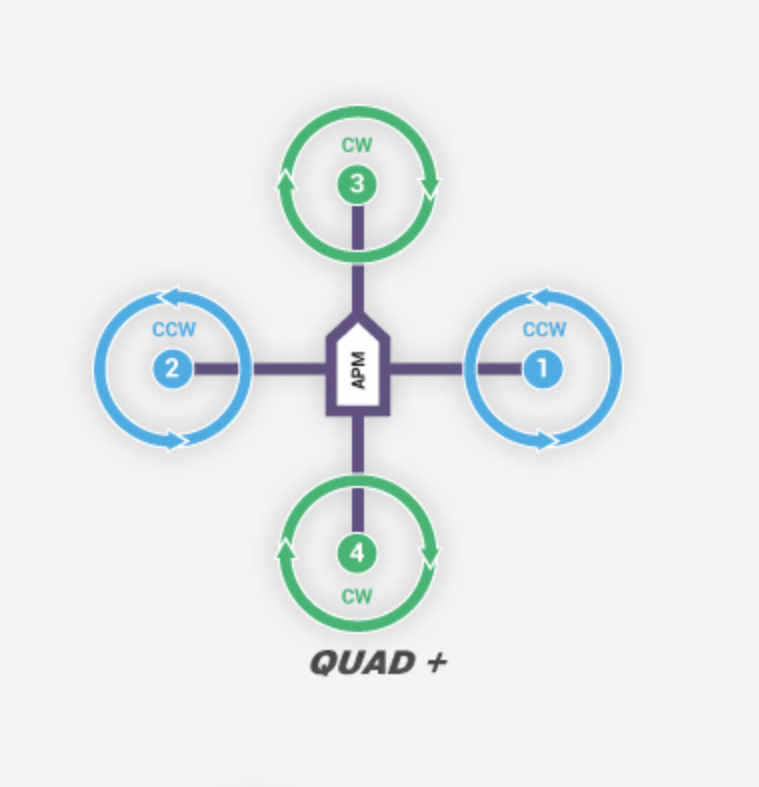
In order to make the quadcopter fly correctly, two of your motors have to be turning in the clockwise direction, and two have to be turning in the counter clockwise direction. I am using the Quad+ layout, so my motor lay out will look like this:
You will also need to wire this accordingly as your APM will need to know which motor is which. I suggest making some sort of label system to label the motor/ESC wire combo with its number so that you can easily tell.
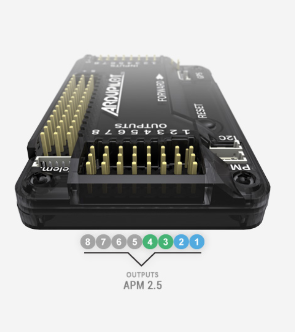
Now connect your motors and ESCs to your APM using the following diagram for a Quad+:
*though the image shows APM 2.5, the inputs remain the same for APM 2.6.
Next, go into Mission Planner with your APM connected to your computer, and go to the motor test under optional hardware.
From there, simply press the test button for each button, and observe that your motors numbering is correct. Note that the motors will not turn in order of 1, 2, 3, 4, but rather, will move in a clockwise direction starting from your front motor. Therefore, Test motor A should turn motor 3, then Test motor B should turn motor 1, then Test motor C should turn motor 4, and then Test motor D should turn motor 2.
Once you have confirmed your setup is correct, remove each input one by one, plug it into the throttle channel in the RC receiver (remember this is usually channel 3, but check your manufacturer's specs to make sure!).
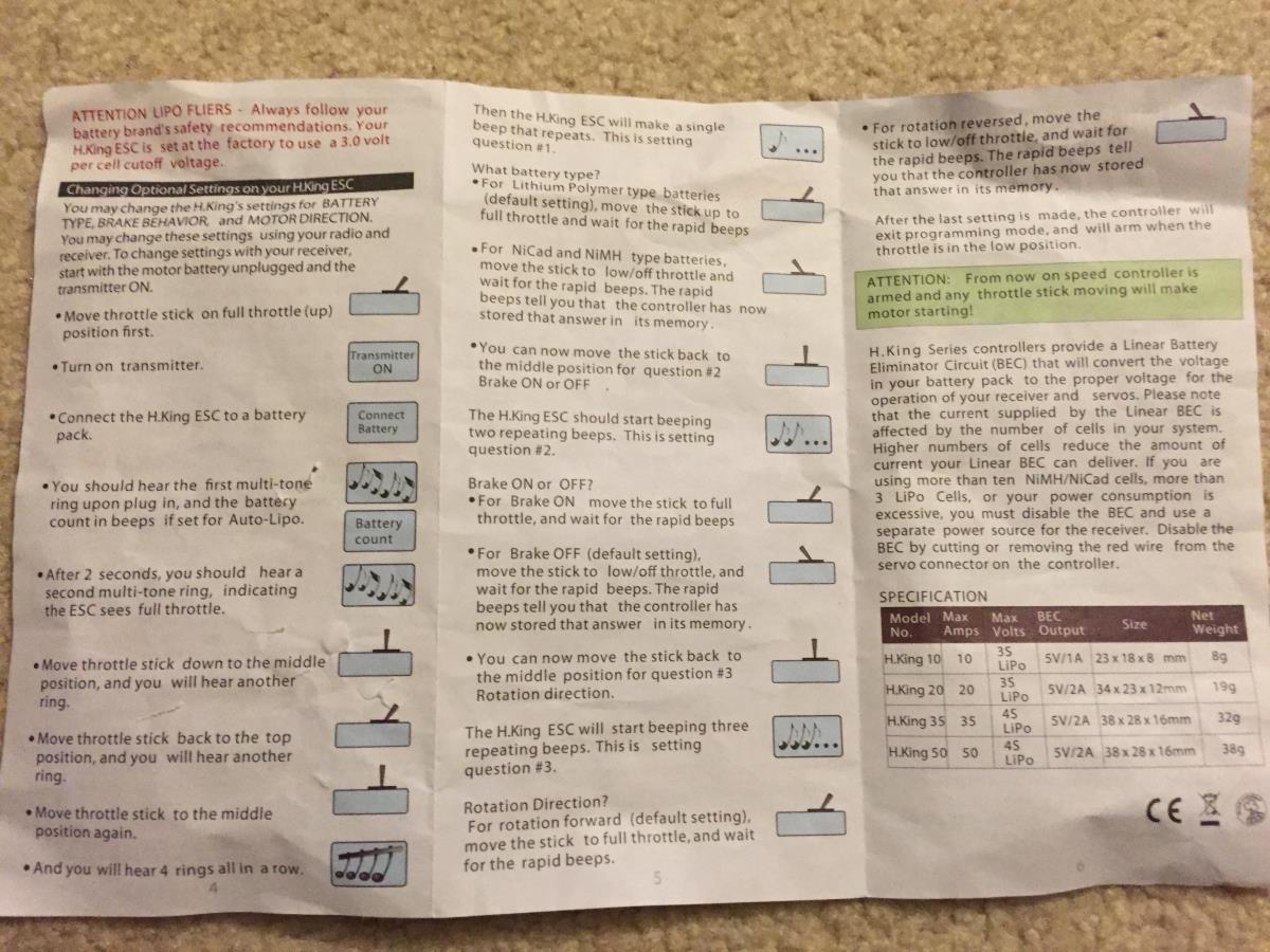
From there, you have to program it using your ESC’s manual. This changes a lot, but it will involve listening to beeps, and moving your throttle stick to essentially move through a menu. The following are the instructions the HobbyKing ESCs I used:
As you can see in the above picture, you will be able to change the rotation of the motor using the ESC. Matching the diagram earlier or Motor 1 and 2 being counter-clockwise while Motor 3 and 4 being clockwise, program your ESC to make sure each motor is turning in the correct direction. Then run the motor test again, to ensure that you did this correctly!
Confirmation Testing
Now let's confirm that we have done everything correctly so far! Load up Mission Planner, connect your APM, and on the horizon viewer, make sure you are getting a GPS Lock. If it says GPS connected but there is no GPS lock, you simply have to wait as the GPS may take some time to get a lock on your position. If it takes more than a few minutes, try resetting the APM using the reset button on top. If there are still issues, try moving your GPS farther away from the electronics and testing to see if interference is your issue.
After, move your quadcopter around, and notice the change in direction on the horizon viewer. If when sitting flat, your horizon viewer does not seem level, you likely will have to re calibrate your accelerometer. If you have a compass handy, such as a compass app on your smartphone, use it to confirm that your external compass is working as well. Finally, run motor tests once more to triple-check your motor direction matches the intended layout, while trying to note which motors are which. If you are using my layout, it is nice to use the names on the sides as points of reference for each motor.
Propeller mounting
Now to the "fun" part--mounting the propellers! This caused me quite the headache, because somehow, the manufacturers switched up the labeling on my propellers. As such, I deca-checked everything yet I was still running into problems flying. On a whim, I decided to switch out the propellers, and it worked!
To install your propellers, you should first take the propeller mount provided with each motor. It will come in a couple different parts. First, you will have the top of the mount, which is a bullet-looking screw. Accordingly, I will refer to this as the bullet screw. Under that, you have a ridged screw that is wedged between the bottom and the bullet screw. I will refer to this as the wedge screw. And finally, you have the shaft screw, which is the long screw with a hole at the bottom to fit onto the motor shaft.
Take your shaft screws, and slide each onto a motor shaft. Then take the wedged screw and slide that on top of the wedged screw, making sure that the side with ridges is facing upward.
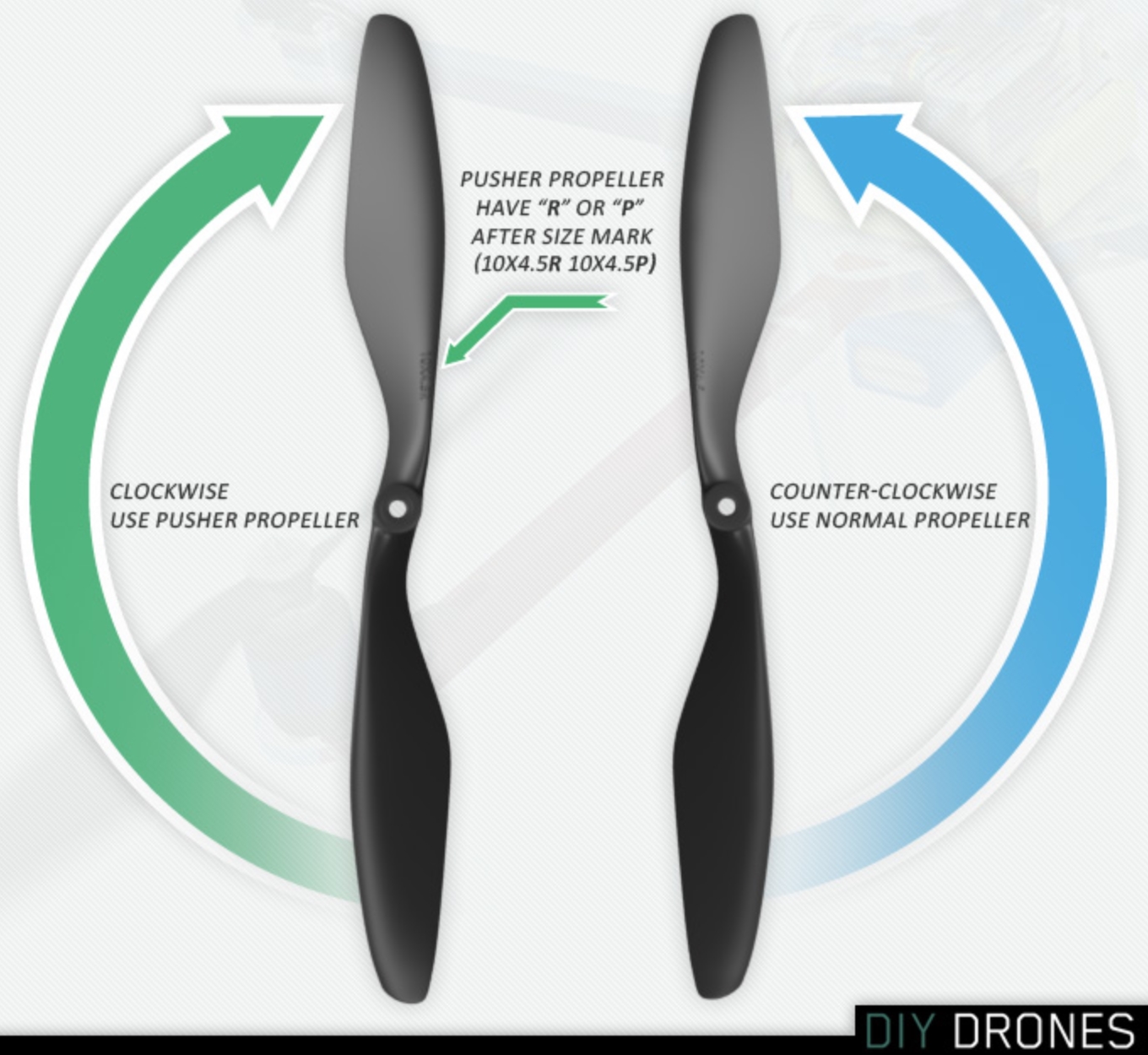
Next, take out your 11x4.7 Slo-fly propelllers, and identify which propellers are clockwise propellers, and which ones are counterclockwise. Typically, the clockwise ones are marked with an R on the writing on the top of the propeller, however, I would not necessarily trust this. Follow the shaping of the propeller in the image below to confirm:
Getting this correct is crucial to getting your quad to fly! Now put each propeller on it's respective turning motor, keeping the lettering facing upwards. In other words, the little marked lettering on the top that says 11x4.7 or 11x4.7R should face the ceiling. Now put the bullet screw on top and tighten it onto the propeller. I suggest taking a little screw driver, pushing it through the small holes on the bullet screw, and tightening this as if you were using a wrench.
One issue I had with this was that my propellers would not stay on! If you get the same motors as I do, you will realize that the propeller mount is not the best. I have found two solutions for this problem.
You can apply Loctite Blue into the hole on the bullet screw and then tighten it on as usual. I would then let it sit for half an hour to let it cure. The packaging says it only needs 10 minutes, however, I prefer to be on the safer side. If you choose this option, make sure to only use Loctite Blue and not Loctite Red or Purple, as Blue is the removable version.
Go to your local hardware store (I went to Home Depot) and find some nylon lock nuts to replace your bullet screws. I had to get M6-1.0 Zinc-plated Nylon Lock nuts to fit on top of the wedge screw. I would suggest taking the screw with you and testing it in the store before buying.
Both of these options works, and I would highly suggest using at least one, however, I would wait to use them before testing the quadcopter to make sure it actually flies.
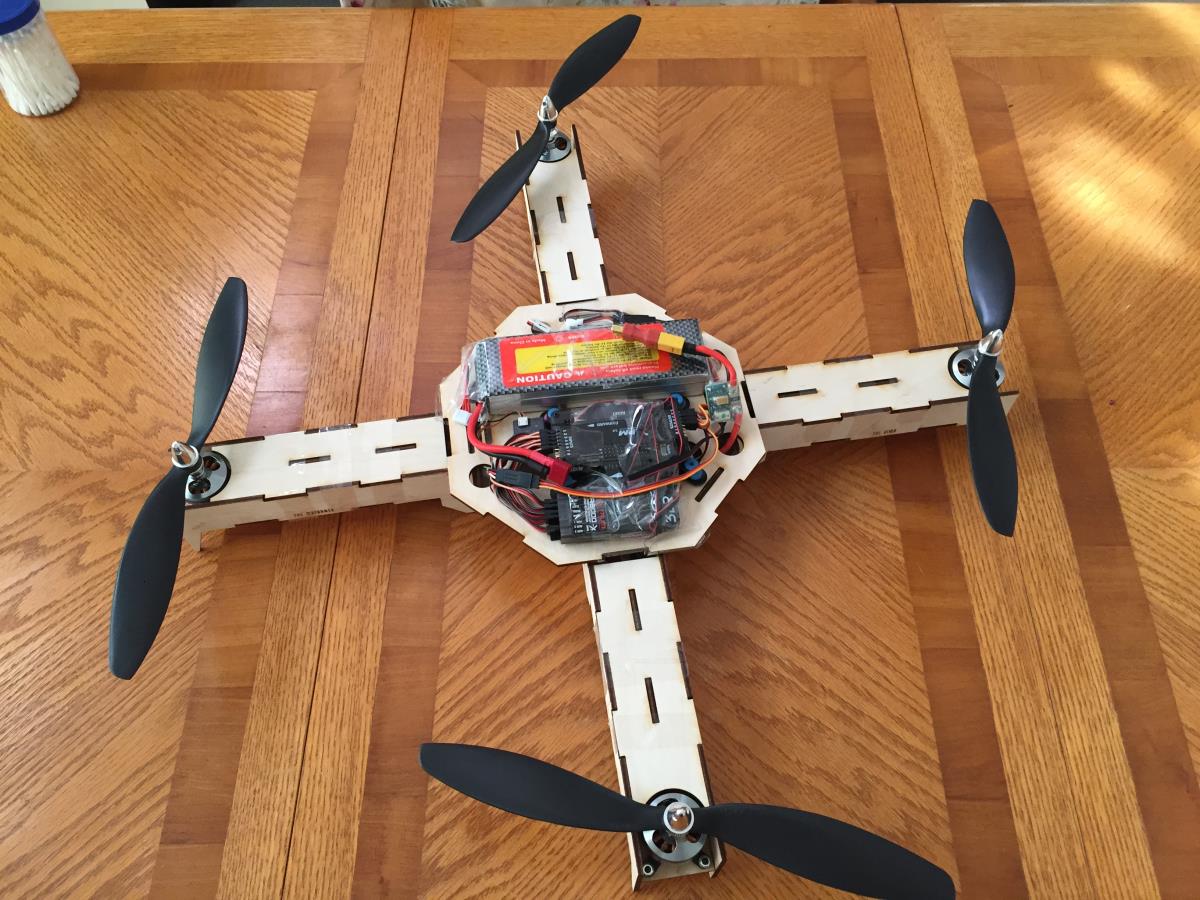
The following is a picture of my quadcopter with the propellers on correctly. You can use this as a reference to make sure your propellers are on correctly as well.
Finishing Touches on Assembly
Almost there! To finish up the quadcopter, complete the following steps:
Put the arm tops on using a removable material (not the CA glue) so that you cover and protect your motor and ESC wires in case of problems, but removable so that if something ends up not working, you can still access all your wires.
Make sure everything fits in and the middle layer of the center console clicks in.
Check to make sure the top will also click in nicely.
Connect your battery to your PDB and APM using the APM Power Module. The quad should begin to beep.
Fit your top layer on, while being sure to orient it correctly so the four screw holes align.
Put your three-inch #8 screws through the holes, and lightly connect a nut to each (not too tight because you will probably want to take it off at times).
As long as there isn't any visible stress on any joints, all the prior steps were followed, and every is connected snugly, you should have a working quadcopter!
Arming your APM and First Test Flight
Now, for the moment of truth! Place your quadcopter in an open space with no one around. I used my empty living room for basic testing as it is carpeted and there is minimal furniture with no one around.
Arm your APM by turning on your RC transmitter (controller) while keeping the throttle stick down. When ready, hold your throttle in the bottom left most area for 5 seconds. Your APM should be armed and ready to fly! If this does not work, try the bottom right most area for 5 seconds.
Very slowly increase the throttle, and you should take off! Try getting the hang of the controls. As someone new to anything like this, I can definitely say that it takes a while to get the hang of. And, voila, you have now built your own quadcopter!
Here's a video of my first functioning test flight!
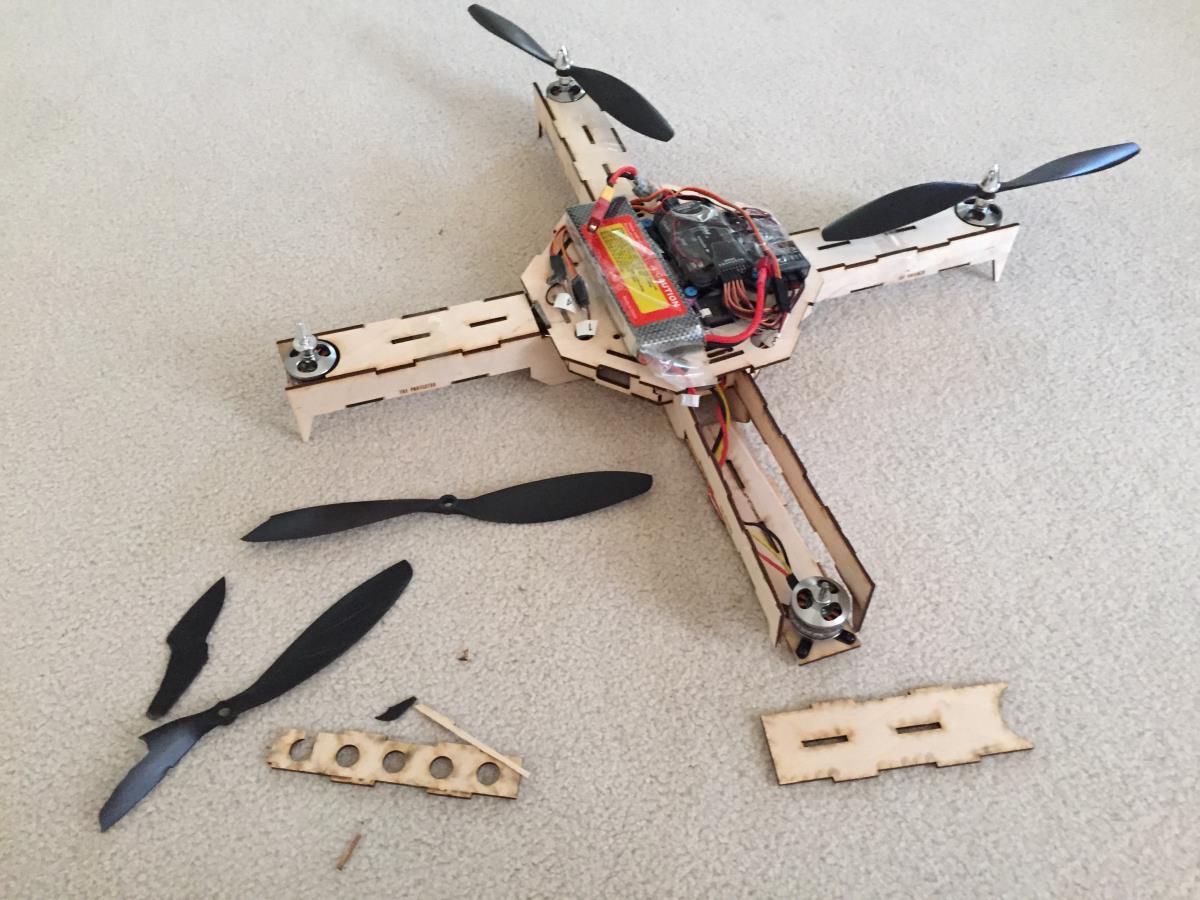
As you can see, it takes off pretty well! I can control movement, among other things, up until the point when the propeller loosens and falls off, causing the quad to fall to the ground. This was before I used Loctite, so if this happens to you, I suggest you follow one of the two strategies I explained in the propeller mounting section.
Troubleshooting Problems On Your First Flight
So your quadcopter doesn't work as you wanted it to? Don't worry about it! I went through so many hours trying to fix problems before I could get mine to work. I'd say that it is more likely than not that your first quadcopter will not work
My motors don't turn!
To troubleshoot this, I would first make sure you are armed! Take off the top layer of the quad, as well as the propellers (for safety), and connect it back up to Mission Planner. Then using your RC transmitter, try practicing arming the device. The horizon viewer should show you when you have successfully armed the device. You can also find more information on arming here. If you are arming successfully, but it is still working, I would try to connect each ESC to the battery individually. If that does not work, I would check your soldering connections between the ESC and the motor.
My quadcopter shoots off like a rocket!
I had this problem too! If you are using my exact setup, this will probably happen to you. What I did was I poked into the full parameter list of the APM, and lowered the THR_MIN down to about 0.08 from 0.13, and this helped it from shooting off so quickly!
My motors turn but it doesn't take off?
I also ran into this issue! Is it something like this?
I spent so many hours trying to fix this. More than likely, it is that your propellers simply aren't on correctly! Make that not only the correct propeller is on, but that the writing side is facing up. If you are 100% sure you have them right--still switch them around anyways! One thing I would do, is assuming your quad doesn't move at all, keep on minimum throttle, and very carefully put your hand 5 feet above the propellers. If you feel air pushing towards you, this is because you have your propellers upside down! Flip them over and try again! If this is not the case, then just rotate each propeller onto it's adjacent motor. It may seem counter-productive to purposefully put your propeller on the wrong motor--but trust me--the manufacturer could have easily mislabeled the propeller. This was the only thing that worked for me in this case!
The Rules of Flying
It is important to know the rules of flying UAVs (quadcopters, drones, etc.). Working with hobby drones has generally been in a legal gray area with only the FAA holding these certain rules against flying. The following infographic should summarize them for you.
Changes I Would Make Looking Back
Looking back at the entire process, the following are changes I would make if I had to re-do it:
I would better plan out the holes on my layer designs, to help me fit each component in snugly
I would a tiny mount on the top layer using standoffs just for the GPS, so that I can limit the interference it gets even further.
I would flash SimonK firmware onto my ESCs for a more stable flight. Here is a quick video showing the the difference it can make
or maybe I could work on writing my own firmware! That would be even better!
Make the battery and power module connector more easily accessible so I do not have to take the top off each time I want to turn on/off or charge the battery.
Changes I Will Make Moving Forward
After building this, I am only more excited as to what I can add and work on in the future. Here are some of my ideas for this quadcopter:
I want to make it controllable via the PS1 controller (potentially with an RC adapter)--which I already got working with my Arduino Micro.
I also want to make my own little power module for my APM so that I do not have to use 3DRs.
I want to look into writing my own basic stabilization algorithm from scratch! I piggybacked off of APM's in-built stablization algorithm with only a few changes on values here and there so that it worked more to my liking, but I definitely want to look into writing my own. Unfortunately, I didn't have enough time to do all of that for this project, but I will absolutely do so in the future.
I would love to mount a camera with gimbal onto this quad. Because the motors I used give me ample power, I should be able to get a very light (and resilient) camera and mount it on to fly!
Closing Remarks
I have to say that this class was definitely something special. I went from not even knowing how to wire a LED blink circuit, to building a Barebones MP3 player and a quadcopter! It is amazing how much can be done with the right guidance and direction. It was an absolute pleasure not only building this quadcopter, but also just being in class and sharing my summer with EE47. There is no better feeling than working really hard to build something, and then finally seeing it work for the first time! I remember when I finally got my quadcopter to lift off--I almost dropped my phone in excitement! And moreover, I learned so much through the entire build process! Thank you for such a wonderful experience--I can honestly say that I am leaving this summer with quite a few more skills than when I began. I look forward to continuing to tinker with electronics using my new-found skills, and am excited to see what other cool things I can build! Again, thank you. EE47 was a great class and I would recommend it to everyone! Have a great next semester!
Special Shout-out
I would like to particularly give a shout out to Samyuktha Challa. Early on in the semester, I was having difficulty soldering and I just couldn't get it right. She sat down with me, even though it wasn't her office hours(!), and taught me how to solder correctly. That little chunk of time she spent teaching me how to do it correctly not only helped me through every single lab, but was honestly the only reason I was able to make all the soldering connections required to make this project successful. I know I told you this in person--but again-- thank you so much, Samyuktha!
We really love how you put in the extra effort to include so many helpful details and tips for the beginner and we really appreciate it! We like how you point out the lessons learnt in hindsight.
You did a good job of clearly stating your POV and how you come up with it . We like how you brainstorm different ideas to come up with your product shape. Both your Verplank diagram and state diagram are good, but may be you can make them a bit more easier to read. We like the instructables-type formatting.
Feel free to send us the link to your Instructable.
It was fun having you this summer and we hope you will get to do much more amazing stuff from here on.
Best wishes,
Samyuktha, David, Dongao, Praveen, Tian, Xiangyu and Zahra


.jpg)


Comments (2)
Samyuktha Challa said
at 8:16 pm on Aug 18, 2015
Hi Neil,
We really love how you put in the extra effort to include so many helpful details and tips for the beginner and we really appreciate it! We like how you point out the lessons learnt in hindsight.
You did a good job of clearly stating your POV and how you come up with it . We like how you brainstorm different ideas to come up with your product shape. Both your Verplank diagram and state diagram are good, but may be you can make them a bit more easier to read. We like the instructables-type formatting.
Feel free to send us the link to your Instructable.
It was fun having you this summer and we hope you will get to do much more amazing stuff from here on.
Best wishes,
Samyuktha, David, Dongao, Praveen, Tian, Xiangyu and Zahra
yifengl said
at 8:01 am on Aug 29, 2015
This is the longest if not the best report I've seen. Did not have time to read everything, but it was amazing how much you did in short time!
You don't have permission to comment on this page.