Point Of View
In today's society the majority of people do not listen to or understand music with the depth or richness which they are intended to. In order to increase
the depth of understanding someone can gain from musical interactions, it would be interesting to add another human sense to the equation. When somebody
experiences something through multiple senses, such as hearing music and seeing light visualizations of it, it allows them to gain a different perspective on
what they are experiencing. This new perspective can provide the user, in this case listener/viewer, a new, different, or deeper understanding of what it is they
are experiencing.
Original Design Ideas
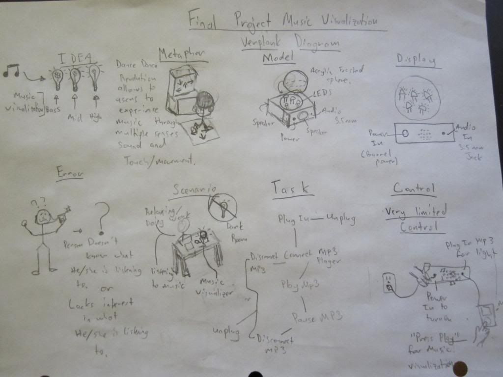
Verplank Diagram
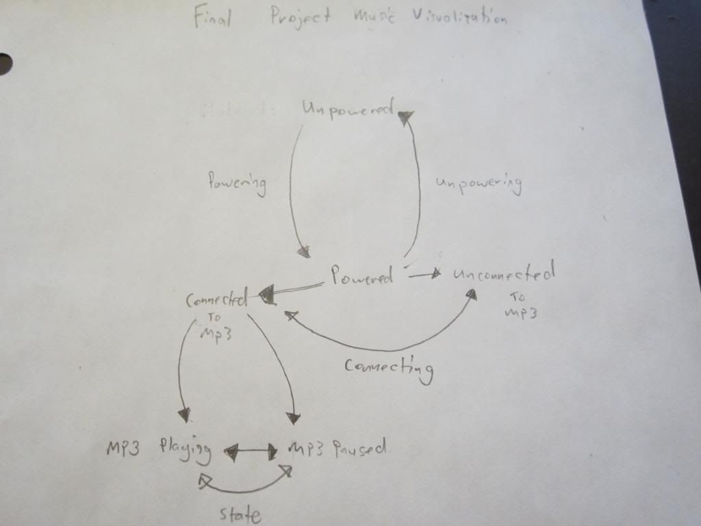
State Diagram
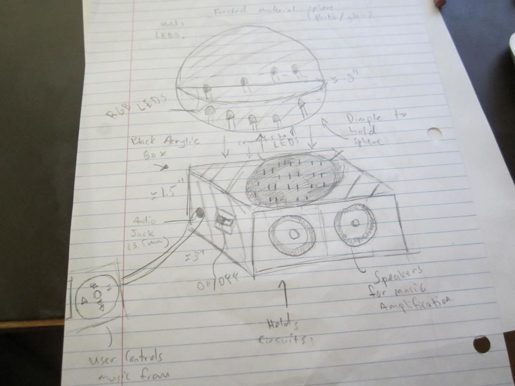
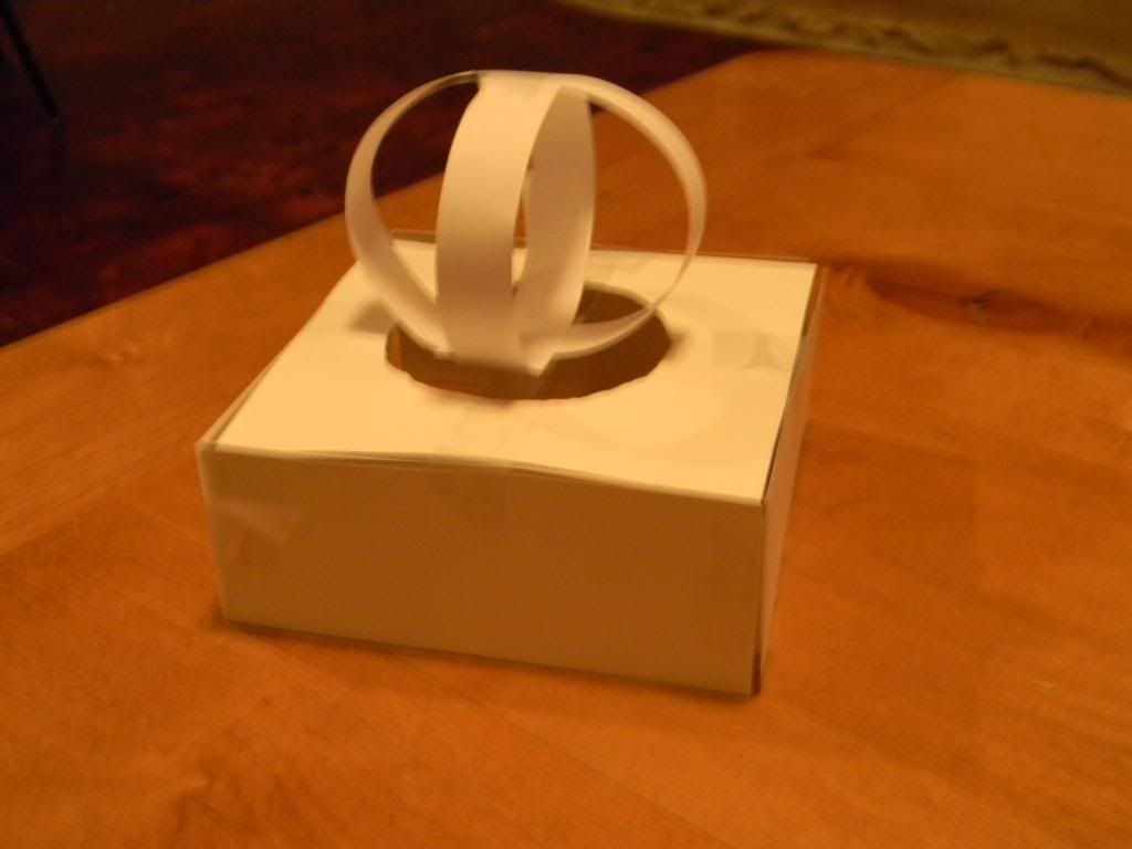
Paper Model Design
Project Code
** Code used to drive the MSGEQ7 (Equalizer Chip) was seen on Xavier Falco's pressplay.pbworks page.
http://pressplay.pbworks.com/w/page/41203030/Graphic%20Equalizer%20Display%20Filter%20(Sound%20analysis).
int analogPin = 0; // read from multiplexer using analog input 0
int strobePin = 11; // strobe is attached to digital pin 2
int resetPin = 12; // reset is attached to digital pin 3
int spectrumValue[7]; // to hold a2d values
int highSounds = 3; // corresponds with the high range of the audio file
int midSounds = 6; // corresponds with the medium range of the audio file
int lowSounds = 5; // corresponds with the low/bass range of the audio file
void setup()
{
Serial.begin(9600);
pinMode(analogPin, INPUT);
pinMode(strobePin, OUTPUT);
pinMode(resetPin, OUTPUT);
pinMode(highSounds, OUTPUT);
pinMode(midSounds, OUTPUT);
pinMode(lowSounds, OUTPUT);
analogReference(DEFAULT);
digitalWrite(resetPin, LOW);
digitalWrite(strobePin, HIGH);
Serial.println("MSGEQ7 test by J Skoba");
}
void loop()
{
digitalWrite(resetPin, HIGH);
digitalWrite(resetPin, LOW);
for (int i = 0; i < 7; i++)
{
digitalWrite(strobePin, LOW);
delayMicroseconds(30); // to allow the output to settle
spectrumValue[i] = analogRead(analogPin);
/* determines what the value of the bass is, and how to
display it to the led for bass by using a map and then
analogWrite function.
*/
if (i == 1) {
int bassValue = map(spectrumValue[i], 200, 900, 0, 255);
analogWrite(lowSounds, bassValue);
}
/* determines what the value of the mid range is, and how to
display it to the led for bass by using a map and then
analogWrite function.
*/
else if (i == 3) {
int midValue = map(spectrumValue[i], 200, 1000, 0, 255);
analogWrite(midSounds, midValue);
}
/* determines what the value of the high range is, and how to
display it to the led for bass by using a map and then
analogWrite function.
*/
else if (i == 5) {
int highValue = map(spectrumValue[i], 200, 950, 0, 255);
analogWrite(highSounds, highValue);
}
if (spectrumValue[i] < 10)
{
//Serial.print(" ");
//Serial.print(spectrumValue[i]);
//delay(10);
}
else if (spectrumValue[i] < 100 )
{
//Serial.print(" ");
// Serial.print(spectrumValue[i]);
//delay(10);
}
else
{
//Serial.print(" ");
//Serial.print(spectrumValue[i]);
// delay(10);
}
digitalWrite(strobePin, HIGH);
}
}
Design Stages
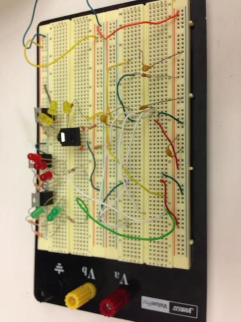
Bread Board prototype
of my final project, minus the Arduino Micro and Graphics Equalizer Chip because they were in the pert board at the time of the picture.
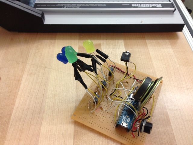
Perf Board stage complete with all components soldered into the pert board.
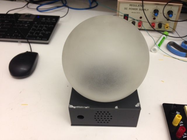
Design of housing meant to hold the perf board and display at the time of the photo the housing is empty.
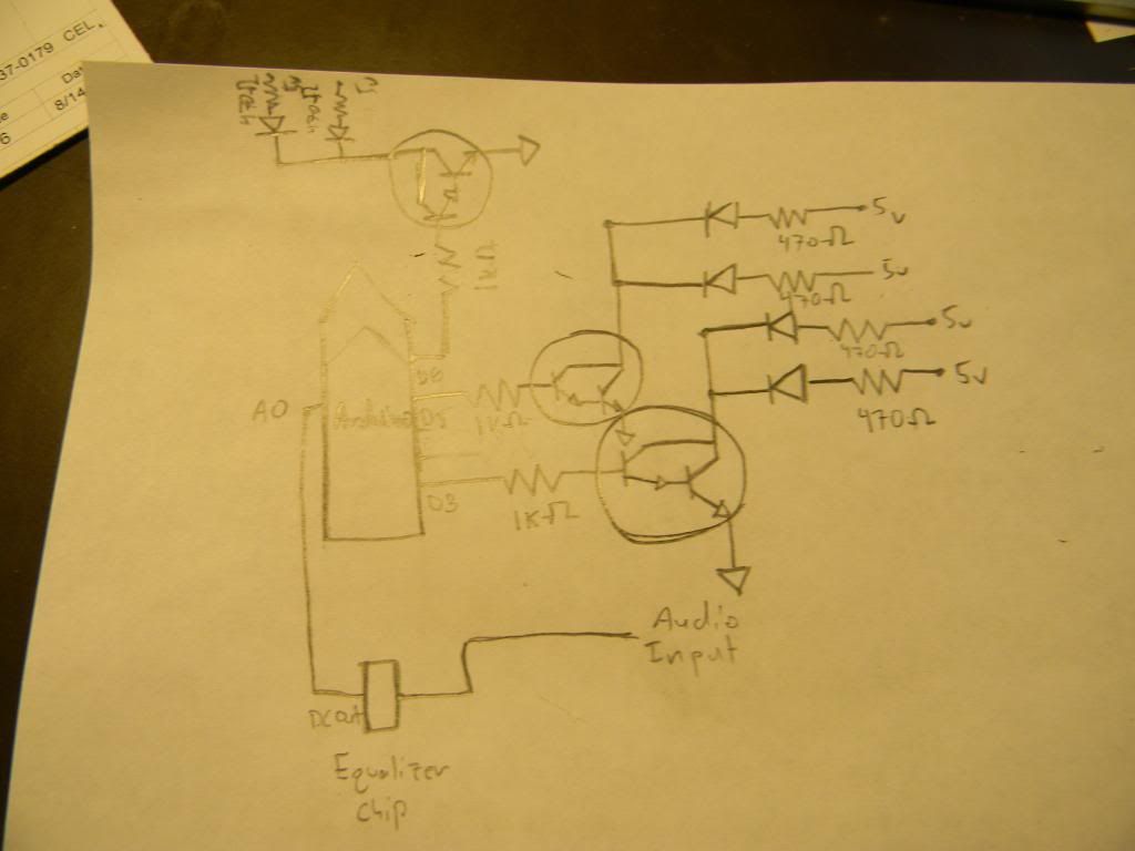
Equalizer to LED schematic using TIP 120 Transistors.
* If you need help on hooking up the msgeq7 (equalizer chip) itself check out this documentation on it http://www.baldengineer.com/projects/msgeq7-simple-spectrum-analyzer/ , It gives all the components necessary to
to hookup the msgeq7 and the schematic of what pins connect to where along with some starter code for your equalizer projects.
Components needed for final project
Micro controller of some kind (I used the Arduino Micro).
Graphics Equalizer Chip - msgeq7 from spark fun.
Components needed to hook up msgeq7
- (5) – 470Ω Resistors (this varies depending on how many lights you want to use, for me I needed 6 resistors because I was using 6 LEDs).
- (1) – 180kΩ Resistor
- (1) – 22kΩ Resistor
- (1) – 33pF Capacitor (Ceramic)
- (1) – 0.01µF Capacitor (Ceramic)
- (2) – 0.1µF Capacitors (Ceramic)
- Jumper Wires
LED's (I used 6, you can use more or less).
Transistors in order to run multiple LEDs (I used TIP120s, this is not optimal, use a lower power transistor if possible, the TIP120 works but is just a bit of overkill for driving nothing but LEDs.
1 k ohm resistors especially if you do use the TIP120s.
Audio jack or input of some kind. (An audio jack seems to be the simplest way to go).
Final Project Video
Extensions and Improvements
If I were to have more time and resources I would look to change a few things in my existing project.
- I had speakers which would amplify the sound of the mp3 directly from the music visualization device. When implementing the speakers, however, I did not have time to assemble very helpful op amp circuit, which rendered my speakers very quiet and almost useless. Due tot his I removed the speakers from the perfboard. Given more time I would have liked to create the op amp in order to make my music visualization an all in one experience.
- On/Off button - Right now the device is on if it is plugged into the wall and off if it is unplugged, I would have liked to implement a switch which allowed the device to be plugged in but remain in an off mode.
- Different modes - I would have also like to add more modes than just music visualization, perhaps a solid white light for just doing work, a color changing and fading light for pure relaxation, and a classic strobe light in addition to the music visualization would have given the project more versatility and a more user friendly experience.


Comments (1)
kdade said
at 2:49 pm on Aug 19, 2013
Dear Cameron,
We like the idea, and you have done a wonderful job prototyping both the physical device (we love the paper model!), and the circuit. Your point of view provides a nice overarching justification for the project, and we would love to see you include some specific answers to the question: "who needs what for what and why?". For instance, you might say, "I need a colorful ambient light display for when I am hanging out with friends late at night." The more specific you can be, the more it will help guide you as you develop your project.
Your report is really well put-together, and we like the captions you have included for each image - they demonstrate your knowledge of the project material and make it easy for anyone to follow along (we especially like the comment about TIP120s).
Overall, this was a great idea, and your execution is spot on. The video shows how beautifully the final product works - you should be really proud!
Best,
Kevin, David, Vivien, Jessica, Matt
You don't have permission to comment on this page.