For my final project, I designed and built a Bluetooth controlled, one-button MP3 player. The original idea for my MP3 player came from a setup that I have used in my home before. With an iPod touch or iPhone, you can control your laptop's iTunes from anywhere in the house over your Wi-Fi network. At home, I often plug my laptop into a speaker system and listen to music from different places in the house, and since I can easily keep my iPod touch in my pocket, I don't have to get up and go back to my laptop every time I want to change the music.
This setup is very convenient, but it has some limitations. First of all, my laptop is much larger than any conventional mp3 player, and oftentimes I need to use it and can't dedicate it solely for music. I would prefer to have a small, dedicated mp3 player that frees up my laptop for other purposes. In addition, I would like to not have to rely on an iPod touch or an iPhone in order to remotely control the music. Instead, I would ideally like to control the mp3 player from my laptop, my phone, and the device itself interchangeably. Finally, I don't want to have to rely on a Wi-Fi connection in order to control my mp3 player--instead, I would like to take it anywhere and still have the full capability to control it.
My solution to these limitations is actually pretty straightforward--build a basic, functional mp3 player, and enhance it with a Bluetooth module that communicates with the Arduino serial. These communications can be sourced from any Bluetooth device--including laptops, smartphones, and even devices that I can build myself!
Here is a video of my finished project in action:
http://www.youtube.com/watch?v=ZY4X6VEC7_I&feature=youtu.be
For a general idea of the materials required for the final project, here is a picture of my disassembled mp3 player:

Starting from the top left corner and moving down the columns, we have a 16 x 2 character LCD display, an Arduino Micro microprocessor (blue), a VS10XX mp3 decoder chip (red), an RGB LED rotary encoder, an HEF 4050 level shifter (shifts the voltage range from 0-5V to 0-3.3V), a microSD card and adapter, ribbon cable, perfboards/wires/male headers/female sockets, a Bluetooth module, an audio jack, and perfboard spacers and screws.
Let's start from the simplest components (a "Hello, world" of sorts...) and move on through to the more involved portions in sequence.
Believe it or not, the most straightforward portion of this project was setting up the Bluetooth communication. Once my parts came in the mail, it only took about an hour and a half of tinkering to produce a functional (albeit simple) Bluetooth device. The Bluetooth module that I selected for this project is a generic Arduino Slave Serial Module from MIB Instruments. It is pretty minimal, with only the Serial talk/read pins and power/ground:
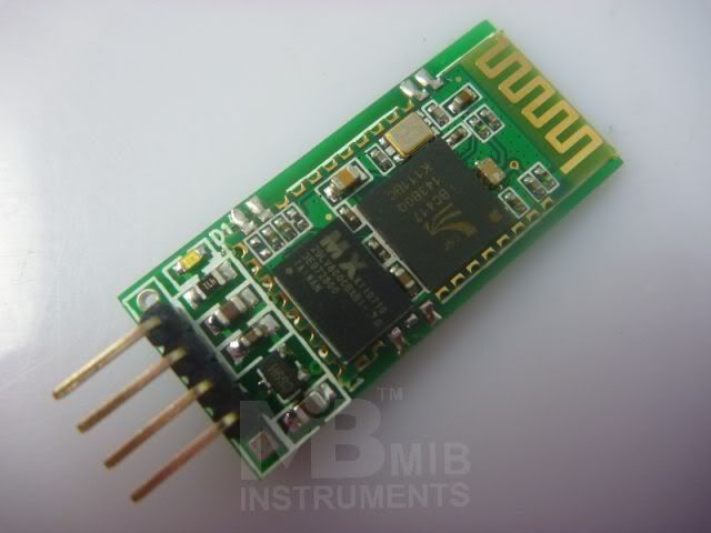
(photo courtesy of MIB Instruments)
The simple feature set of this module makes the Bluetooth module very easy to work with--basically all you have to do is connect the pins to the Arduino and pair it to the correct device (in this case, my laptop). Here is the schematic:
| Arduino |
TX |
-------> |
RXD |
Bluetooth Module |
| RX |
<------- |
TXD |
||
| GND |
-------- |
GND |
||
| 5V |
-------- |
VCC |
Arduino TX -------> RXD Bluetooth Module
RX <------- TXD
GND -------- GND
5V -------- VCC
To communicate over Bluetooth, simply read and write Serial data using the "Serial1" object rather than the "Serial" object in the Arduino sketches.
Here is a fun sketch that you can use to test the correct functioning of your Bluetooth module: (if you have access to a speaker, hook one end up to pin 9 on the Arduino and the other end to ground. If you don't have a speaker, this sketch will still work as is)
/*
Morse Code Bluetooth
This sketch creates a Bluetooth morse code clicker. To translate a message to morse code, power up the device (it does not have to be physically connected to your computer) and open the Arduino Serial Monitor to the correct Bluetooth port (it should be something like /dev/tty.linvor-DevB or /dev/cu.linvor-DevB). You can type any (lowercase) message and send it over the Serial port, and the Arduino will respond with a morse code representation of the message. If you have a speaker connected to pin 9, this message will also be played on the speaker.
Copyright Shane Leonard (2013) under the Creative Commons License. This software is released as open source, so you have full permission to duplicate and redistribute any portion of this code.
*/
int speakerPin = 9;
// letters are a max of 4 morse characters
String alphabet = "abcdefghijklmnopqrstuvwxyz1234567890";
String morseAlphabet[] = {".-", "-...", "-.-.","-..",".","..-.","--.",
"....","..",".---","-.-",".-..","--","-.","---",".--.","--.-",".-.",
"...","-","..-","...-",".---","..--",".---","-..",".----","..---",
"...--","....-",".....","-....","--...","---..","----.","-----"};

int NUM_CHARS = 36; // length of the 'alphabet'

int t_int = 50; // duration of the morse code dot

void playTone(int tone, int duration) {
   for (long i = 0; i < duration * 1000L; i += tone * 2) {
     digitalWrite(speakerPin, HIGH);
     delayMicroseconds(tone);
     digitalWrite(speakerPin, LOW);
     delayMicroseconds(tone);
   }
}
void playNote(char note, int duration) {
   char names[] = { 'c', 'd', 'e', 'f', 'g', 'a', 'b', 'C' };
   int tones[] = { 1915, 1700, 1519, 1432, 1275, 1136, 1014, 956 };

   // play the tone corresponding to the note name
   for (int i = 0; i < 8; i++) {
     if (names[i] == note) {
       playTone(tones[i], duration);
     }
   }
}
void dot() {
   Serial1.write('.');
   digitalWrite(13, HIGH);
   playNote('c', t_int);
   digitalWrite(13, LOW);
   delay(t_int);
}
void dash() {
   Serial1.write('-');
   digitalWrite(13, HIGH);
   playNote('c', 3 * t_int);
   digitalWrite(13, LOW);
   delay(3 * t_int);
}
void letter_space() {
   Serial1.write(' ');
   delay(3 * t_int);
}

void word_space() {
   Serial1.write('/');
   delay(7 * t_int);
}

String charToMorse(char ch) {
   if (ch == ' ') return "/"; // word space

   for (int i = 0; i < NUM_CHARS; i++) {
     if (ch == alphabet[i]) {
       return (morseAlphabet[i] + " "); // the space indicates the end of a letter
     }
   }
   return "/"; // return a word space by default
}
void playMorse(String morse) {
   for (int i = 0; i < morse.length(); i++) {
     char ch = morse[i];
     if (ch == '.') dot();
     else if (ch == '-') dash();
     else if (ch == ' ') letter_space();
     else if (ch == '/') word_space();
   }
}
void setup() {
   Serial1.begin(9600);
   pinMode(speakerPin, OUTPUT);
}

void loop() {
   while(!Serial1.available()) {}
   char ch = Serial1.read();
   String morse = charToMorse(ch);
   playMorse(morse);
}
Once that sketch is working, you can start collecting and testing the other components of the circuit. Before adding the SD card, let's hook up the LCD screen so that debugging will be easier for future tests. The LCD should be wired to the Arduino according the diagram below:
| Arduino |
GND |
--> | 1 |
LCD |
| 5V |
--> | 2 |
||
|
5V | | 10 kOhm POT | | GND |
--> |
3 |
||
| 12 |
--> |
4 |
||
| GND | --> | 5 | ||
| 11 | --> | 6 | ||
| 7 | --> | 11 | ||
| 6 | --> | 12 | ||
| 5 | --> | 13 | ||
| 4 | --> | 14 | ||
| 3.3V | --> | 15 | ||
| GND | --> | 16 |
When the LCD and Bluetooth Module are both properly working, go ahead and add the HEF 4050 and the SD card to the mix. First, solder right-angle headers to the SD card adapter like so:

Then make the following connections:
| microSD card | |
Connection |
| MISO | --> | Arduino MISO (MI) |
| GND | --> |
GND |
| SCK |
--> |
4050 Pin 2 |
| 3.3V+ |
--> |
3.3V |
| GND | --> | GND |
| MOSI | --> | 4050 Pin 4 |
| CS | --> | 4050 Pin 6 |
| 4050 | |
Arduino |
| Pin 1 | --> | 3.3 V |
| Pin 3 | --> | Arduino SCK |
| Pin 5 |
--> |
Arduino MOSI (MO) |
| Pin 7 | --> | Arduino SS |
| Pin 8 | --> | GND |
To ensure your setup is working correctly, try out the following code:
/*
   SD card file dump

  This example shows how to read a file from the SD card using the
  SD library and send it over the serial port.

  The circuit:
  * SD card attached to SPI bus as follows:
  ** MOSI - pin 11
  ** MISO - pin 12
  ** CLK - pin 13
  ** CS - pin 17 (listed on Micro as SS)

  created  22 December 2010
  by Limor Fried

  modified 9 Apr 2012
  by Tom Igoe

  modified 1 May 2013
  by Harry Johnson

  modified 11 June 2013
  by Shane Leonard

  This example code is in the public domain.
  */

 #include <SPI.h>
 #include <SD.h>

//On the Arduino Micro, the SS pin is defined in software as pin 17.
 const int chipSelect = 17;

void setup()
{
  // Open serial communications and wait for port to open:
   Serial.begin(9600);

   delay(1000); //this 1 second delay isn't strictly speaking necessary, but it seems to smooth over the USB serial monitor a bit.
   while (!Serial) {
     ; // wait for serial port to connect. Needed for Leonardo only
   }

   Serial.print("Initializing SD card...");
   pinMode(17, OUTPUT); //set SS pin as output.

   // see if the card is present and can be initialized:
   if (!SD.begin(chipSelect)) {
     Serial.println("Card failed, or not present");
     // don't do anything more:
     return;
   }

   Serial.println("card initialized.");

   initializeFile();

   // open the file. note that only one file can be open at a time,
   // so you have to close this one before opening another.
   File dataFile = SD.open("datalog.txt");

   // if the file is available, write to it:
   if (dataFile) {
     while (dataFile.available()) {
       Serial.write(dataFile.read());
     }
     dataFile.close();
   }

   // if the file isn't open, pop up an error:
   else {
     Serial.println("error opening datalog.txt");
   }
}


// Ensure that the file "datalog.txt" exists and that it is initialized with
// sample data
void initializeFile() {
   if (SD.exists("datalog.txt")) {
     SD.remove("datalog.txt");
   }

   File dataFile = SD.open("datalog.txt", FILE_WRITE);
   dataFile.write("This is a sample sentence to make sure your SD card is set up correctly.");
   dataFile.close();
}

void loop()
{

}
Next is the MP3 decoder. Make the following connections: (based on Lab 6--Barebones MP3 Player)
| Decoder | Connect |
Connection |
| CS | --> | 4050 Pin 15 |
| SCLK | --> | 4050 Pin 2 |
| SI | --> | 4050 Pin 4 |
| SO | --> |
Arduino MISO |
| VCC | --> | 3.3V |
| GND | --> | GND |
| BSYNC (DCS) | --> | 4050 Pin 12 |
| DREQ | --> | A2 |
| RST | --> | Arduino Reset |
Retain your previous 4050 wiring, add if necessary
| 4050 | |
Arduino |
| Pin 3 | --> | Arduino SCK |
| Pin 5 |
--> |
Arduino MOSI |
| Pin 7 | --> | Arduino SS |
| Pin 14 | --> | A0 |
| Pin 11 | --> | A1 |
| Decoder | Connect |
Audio Jack |
| LEFT | --> | Pin 2 (TIP) |
| GBUF | --> | Pin 1 (GND on jack NOT Arduino Micro GND) |
| RIGHT | --> | Pin 3 (RING) |
Almost there! The final component is the RGB rotary encoder.
For the 3 pin side of rotary encoder, connect the outer pins to Arduino pins A and B, and the middle pin to ground. Hook up the following circuit: (However, instead of Blue -> A7, connect Blue -> 13)

Finally, download the VS1053.zip library and my MP3_Brain sketch. Replace the this code to the Arduino and add some songs to the SD card. You're done! Here are some pictures from my project:


