Thomas Carney
MP3 Final Project Writeup-Variable Audio Channel Outputs
Introduction:
The purpose of my final MP3 project was to be able to switch audio outputs to the different headphones based on the table below.
| Mode | Left Earphone |
Right Earphone |
| 1 | Left Channel Audio |
Right Channel Audio |
| 2 | Left and Right Channel Audio |
No Audio |
| 3 | No Audio |
Left and Right Channel Audio |
| 4 | Left and Right Channel Audio |
Left and Right Channel Audio |
These various outputs sought to address the problem of switching earbud configurations depending on the user's surroundings. When a user is in his room listening to music, he is more likely to be in Mode 1 where both of his earbuds are in, and he can listen to the Left and Right Channel audio. It is important to note that the Left and Right Channel audios contain different audio tracks, based on the recording location of the left and right microphone respectively when the artist is recording his music. When a user is biking or driving a car, however, he may only have one earbud in because he must be able to hear emergency service vehicles. While the single earbud enhances safety, unfortunately, the user is not able to hear part of the song with a traditional MP3 player. My MP3 player, on the other hand, allows the user to switch to either mode 2 or mode 3 depending on which earbud the user would like to remove and is still able to appreciate the full audio of the song he is listening to. I created this MP3 player by running the left and right outputs from the MP3 decoder chip to an OP AMP adder circuit and then outputting the signal to either the left or right earphone wires using an analog multiplexer. Because the analog multiplexer has a 60 ohm output resistance associated with it, the output signal was then fed through a voltage buffer to remove this decrease in output resistance. This 60 ohm resistance was detrimental to our signal because we sought to power audio speakers with a resistance of around 8 ohm and hence the 60 ohm added resistance increased the new "speaker" by almost an order of magnitude. The MP3 player was enclosed in an acrylic case and was powered externally by a power supply because during the construction of our MP3 player we accidentally fried the voltage regulator chip on the arduino.
Video of Final MP3 Player:
Design Origin:
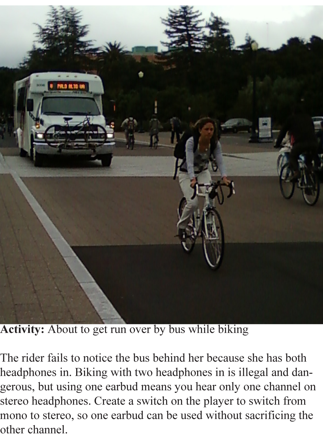
The idea for my MP3 player design came from completing the assignment for class where we went out into the world and attempted to observe problems with current MP3 player use. One scenario I noticed is pictured above where the biker is about to get run over by the bus because she is clueless that it is coming from behind. Although hard to see, she was wearing headphones and could not hear the bus behind her.
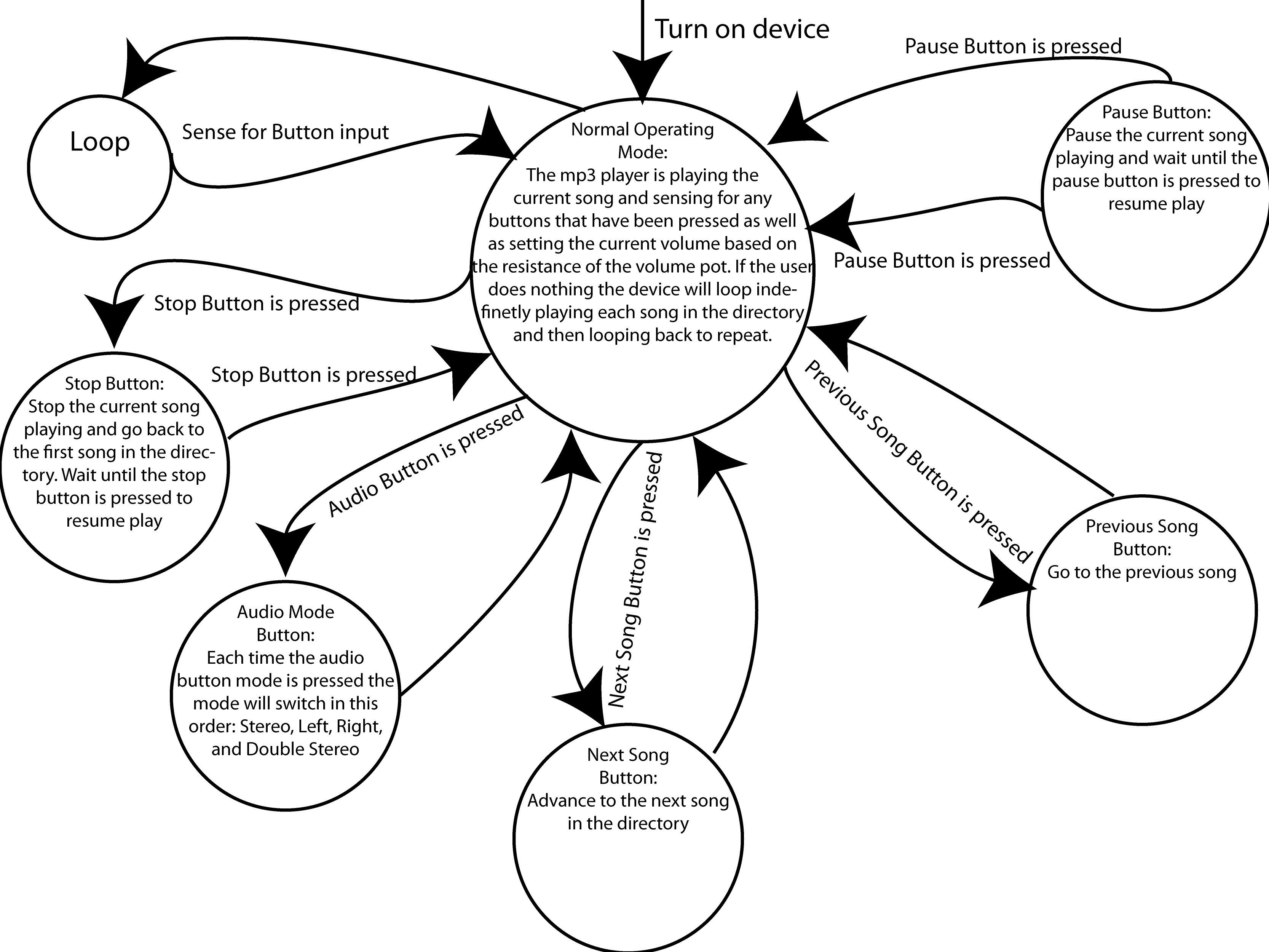
Verplank Diagram:
As an assignment for class we constructed a Verplank diagram of our design which is seen below.

Ideas:
During the paper prototype and other idea assignments in class I thought up numerous ideas. The first idea was to include some sort of GPS module to track a user's movements because the idea behind switching the stereo to mono audio output was to increase the general mobility of the user. I eventually decided that I would not have enough time to implement the GPS feature. I also considered attaching a flex sensor to the heaphones to change the audio output instead of a physical switch such that when the user took one of the earbuds out of his ear, the audio output mode would automatically change to the correct audio output. While the idea seemed promising, when I attached a flex sensor to the heaphone wire, the setup looked gaudy and bulky and hence I did not pursue this design further. If a flex sensor could be integrated more discretely into the headphone wire than I would have pursued this idea further. I also debated between various switches for the audio mode switch and decided a simple cycling button would be best because the user could easily change modes and not worry about having to position a switch exactly in the right place to get the mode he wished. At this stage I also decided that I wanted a previous song, next song, pause button, stop button, and play button. Eventually I merged the play and stop button into one button to save space on my MP3 player and save pins on the Arduino. Moreover, I decided that instead of having a menu with multiple sections I instead would have an extremely simple menu that would display the current song playing, the volume level, and the current audio mode. In addition, I would have liked to make a voltage indicator that output whether the battery was low based on a CV curve but I ran out of time to implement this feature.


State Diagram:
A state diagram of my MP3 player functions.
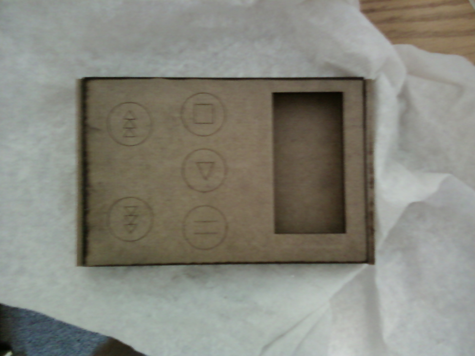
 Case Protoype:
I constructed a case prototype to understand how to use the laser cam in room 36 and to get general ideas on the design. I ended up changing the buttons by combining the stop/play button and inserting an audio mode button instead. The general jointed box design remained the same when I finally constructed my MP3 player out of acrylic.

Creating the MP3 Player:
First, I created the barebones mp3 player as described in lab 6. The VS1033D MP3 Decoder chip was wired to the arduino as follows
| Decoder | Connect |
Arduino |
| CS | Level Shifter |
Pin 5 |
| SCLK | Level Shifter | Pin 13 (SCLK) |
| SI | Level Shifter | Pin 11 (MOSI) |
| SO | 10kOhm Resistor--> |
Pin 12 (MISO) |
| VCC | --> | 3.3V |
| GND | --> | GND |
| BSYNC | Level Shifter | Pin 14 (DCS) (A0) |
| DREQ | --> | Pin 15 (A1) |
| RESET | Level Shifter |
Pin 6 |
The Nokia_5110_LCD was connected to the Arduino as follows
| Graphical LCD | Connection |
Arduino |
| LED | 100 Ohm Resistor --> |
5V |
| SCLK | Level Shifter | Pin 13 (SCK) |
| DN(MOSI) | Level Shifter | Pin 11 (MOSI) |
| D/C | Level Shifter | Pin 7 |
| RST | Level Shifter | Pin 8 |
| SCE | Level Shifter | Pin 9 |
| GND | --> | GND |
| Vcc | --> | 3.3V (NOT 5V) |
The SD card was connected to the Arduino as follows:
| microSD card | Connection |
Arduino |
| CS | Level Shifter | Pin 10 (CS) |
| MOSI | Level Shifter | Pin 11 (MOSI) |
| MISO |
--> |
Pin 12 (MISO) |
| SCLK |
Level Shifter | Pin 13 SCLK |
Level shifters were used because I developed problems as I begun to connect more and more components to the Arduino. The level shifters also helped to simply connections by eliminating the resistors. In this case, a level shifter was used to change from the 5V logic of the Arduino to the 3.3 V logic needed for the MP3 decoder chip, SD card, and LCD screen.
After connecting all of the basic MP3 parts together I proceeded to engineer the volume control. A potentiometer was wired to the Arduino analog input so that by changing the resistance, the volume was changed as well. I also developed a visual indicator based on the idea of the cell phone signal(more bars for more signal) to indicate the current volume level on the main screen. The code can be seen in the following sections.
The stop button was achieved by setting a playMusic boolean to false such that when the button was pressed, the boolean was set to false and the music loop would not play, and when the button was pressed again, the boolean was set to true and the music loop could proceed. The pause button was achieved in a similar fashion except it's boolean was set via an interrupt to a volatile boolean which would cause the current song loop to constantly cycle without playing any more bytes of the currently opened file until the user pressed the button again. The next button was achieved by breaking out of the current song loop and simply allowing the loop to proceed to the next song. The previous song button was achieved by subtracting 3 from the current index of the song playing because the program first had to break out of the initial loop at say i=1, go through the beginning of the loop again to reach the actual previous song code to give i=2 where 3 was subtracted to give i=-1, and then allowed to proceed to the start of the loop again to give i=0 for the current song playing.
After I created the code for buttons I posted it online to the wiki website in order to help other students with their general interfaces. Several students in the lab used and modified my code for their own projects.
Creating the Variable Audio Outputs Using Op Amps and Analog Multiplexers:
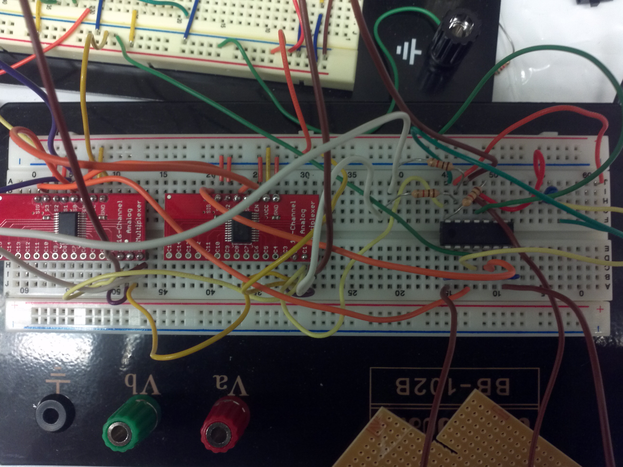
First, we took two 16-Channel Analog/Digital Multiplexer/Demultiplexer CD74HC4067 chips from Spark Fun and designated one to control the left earphone output and the other to control the right earphone output. The middle ground output on the headphone jack was set to the virtual ground coming from the MP3 decoder chip which was measured by the oscilloscope to be at 1.2 V. We designated three unique signals to use for our audio multiplexer: the individual signal (L or R), the combined signal (L+R), and ground (0 V). These three signals were wired up to the chips as follows:
| Input |
Left Earphone Multiplexer |
Right Earphone Multiplexer |
| C0 |
Left Audio |
Right Audio |
| C1 |
Left+Right Audio |
Ground |
| C2 |
Ground |
Left+Right Audio |
| C3 |
Left+Right Audio |
Left+Right Audio |
VCC on the audio multiplexer was set to 5V, the enable pin was set to ground to allow the multiplexer to work, and we used two digital pins D0 and D1 to control the switching of the input signals. The idea of switching the C1 and C2 signals between the two multiplexers allowed us to only have to use two digital outpins on the arduino to control the audio output mode. We were able to use the same output signal on the arudino, for example (low high) to select C1 on the multiplexer input pins, to select the combined signal for the left earphone and ground for the right earphone. Unfortunately, the audio multiplexer had a 60 ohm resistance associated with it's output and thus we ran the output through a simple voltage buffer op amp circuit, (courtesy Wikipedia), to remove this 60 ohm resistance. Although for certain applications this resistance could be considered insignificant, for audio applications, it is not uncommon to drive 8 ohm loads, and thus adding 60 ohms to the output increases the load by almost an order of magnitude. I would like to note that the op amp used was the LM324N. Moreover, V++ for the op amp was set to be 5V and V-- was set to be 0V for all of the op amp circuits used in my MP3 player. In addition, the "ground" drawn in these figures is not the real 0V ground, rather the 1.2 virtual ground. This virtual ground was chosen to allow the signal to have negative and positive peak amplitudes and to prevent them from hitting the rails of the op amp.
The combined left and right signal was created using a summing amplifier op amp circuit as seen here  (modified from Wikipedia), where R1, R2, and RF are all equal to 500 ohms in order to minimize the thermal noise caused by the resistors and to give a unity gain when adding the signals. In this diagram V2 and V1 are the left and right audio channel inputs. Although we tried numerous capacitors in order to improve the signal quality, we found no significant increase in signal quality and hence did not include any in our final design. We did however, include a capacitor between power and ground to stabilize the power around the op amp.
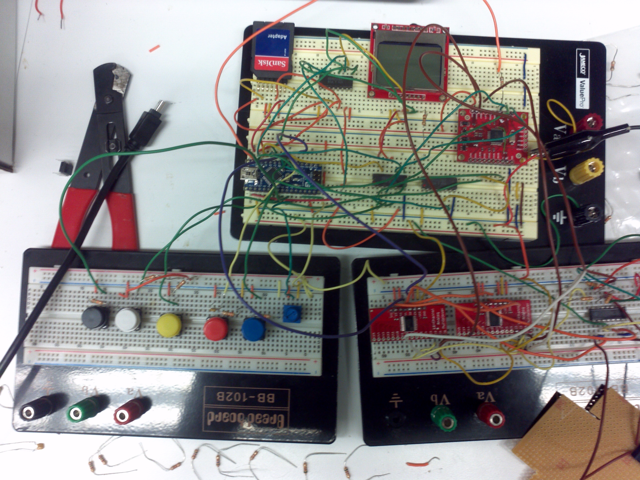
An image of the breadboard MP3 player and a zoomed in picture of the audio circuit that combines the signals and selects the correct channel to output is shown below.
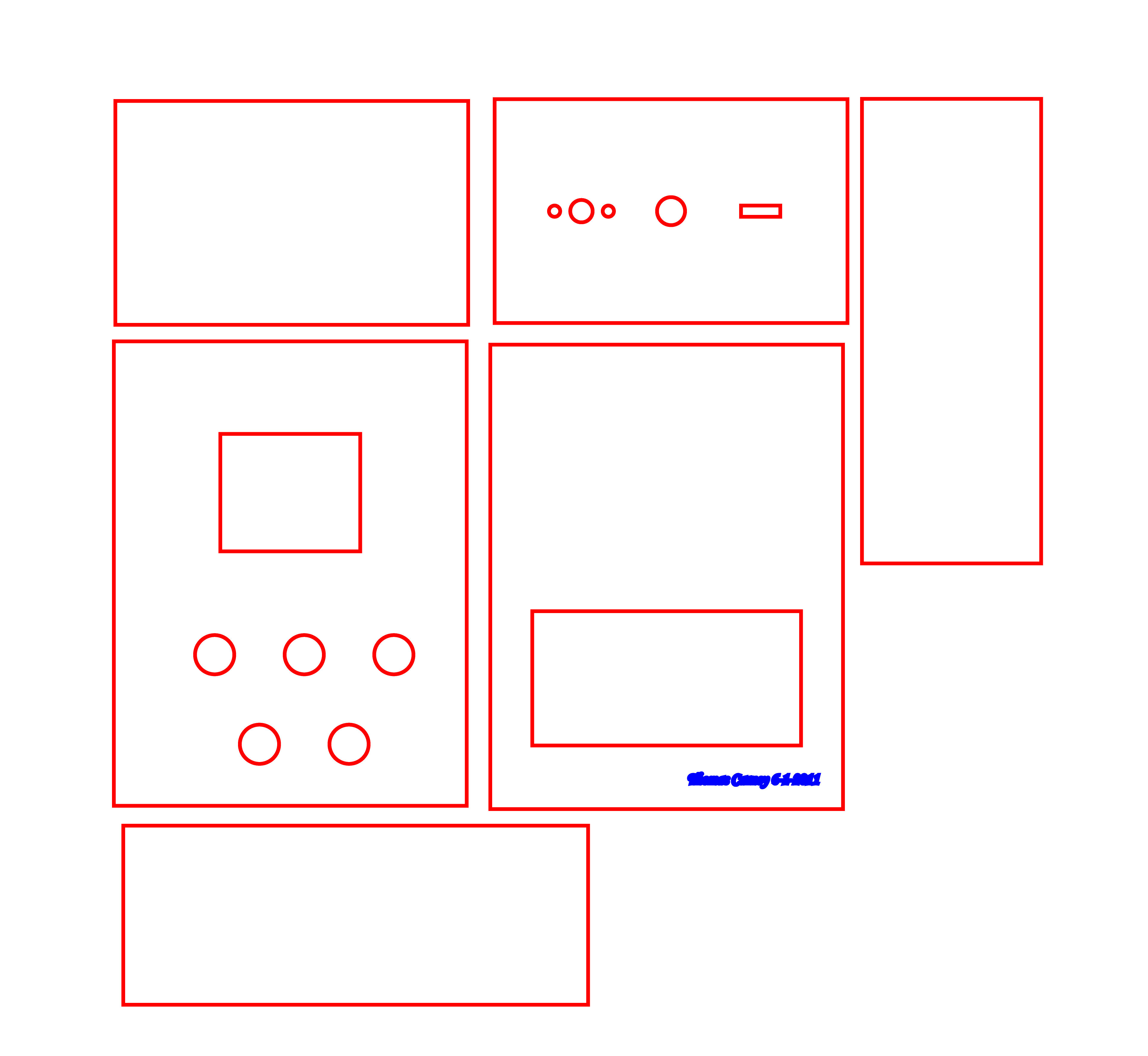
I then proceeded to solder the entire board onto a double stacked PCB board which went very slowly and for future students I would recommend starting much sooner. I also soldered the SD card to the bottom of the first level board such that the card could be accessed by the user if he wanted to add or remove songs from the final enclosed MP3 player. A case made of acrylic was fabricated using the laser cam in Room 36 for our board and an image of the AI file, with the line widths thickened for viewing ease, is shown below.
A video of the finished soldered MP3 player working outside the case can be viewed here:
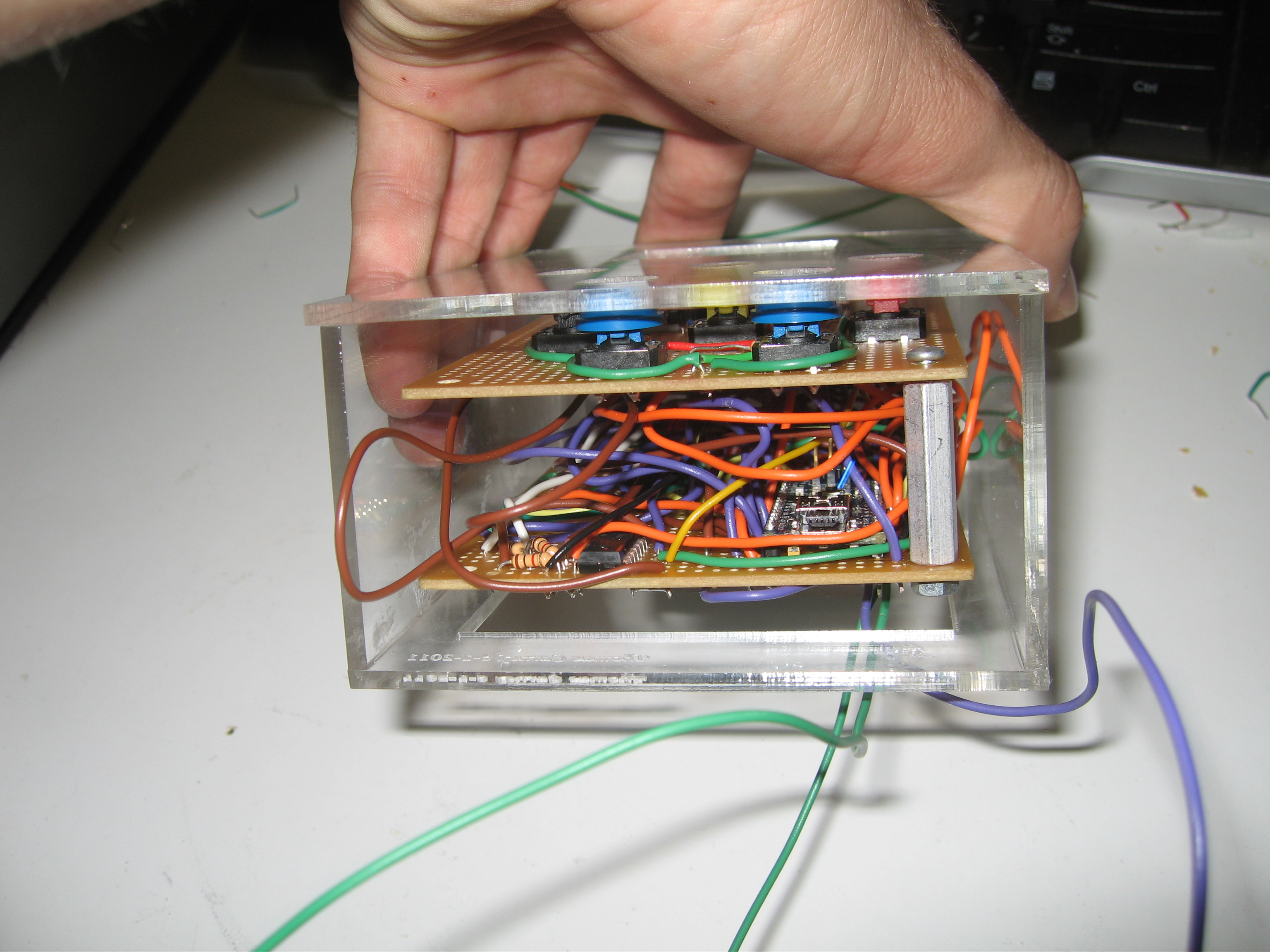
One can clearly observe the various holes in the top of the case as seen in the above picture. One of the holes is for a power switch; however, while I was trying to install a battery system for the MP3 player to be portable, I accidentally destroyed the voltage regulator chip on my Arduino, hence for all future operations, my MP3 player has to be run off a power supply, thus rendering the power switch useless. The acrylic pieces were assembled using acrylic cement and the volume pot, headphone jack, and power switch were attached to the interior of the case using super glue. To further add to the demise of the power switch I also super glued it shut. In addition, during the surge where my voltage regulator chip was blown, one of my audio multiplexer chips blew as well and hence I had to desolder and solder on a new chip, a painful experience due to the lack of space on my board. Another interesting point to note was that when I pressed the double layer together the stop button stopped to work; however, when the two layers were allowed to have a lot of space between them there was no problem. I found a medium between these two extremes by allowing the two boards to fill the void between the top and bottom acrylic pieces of my case.
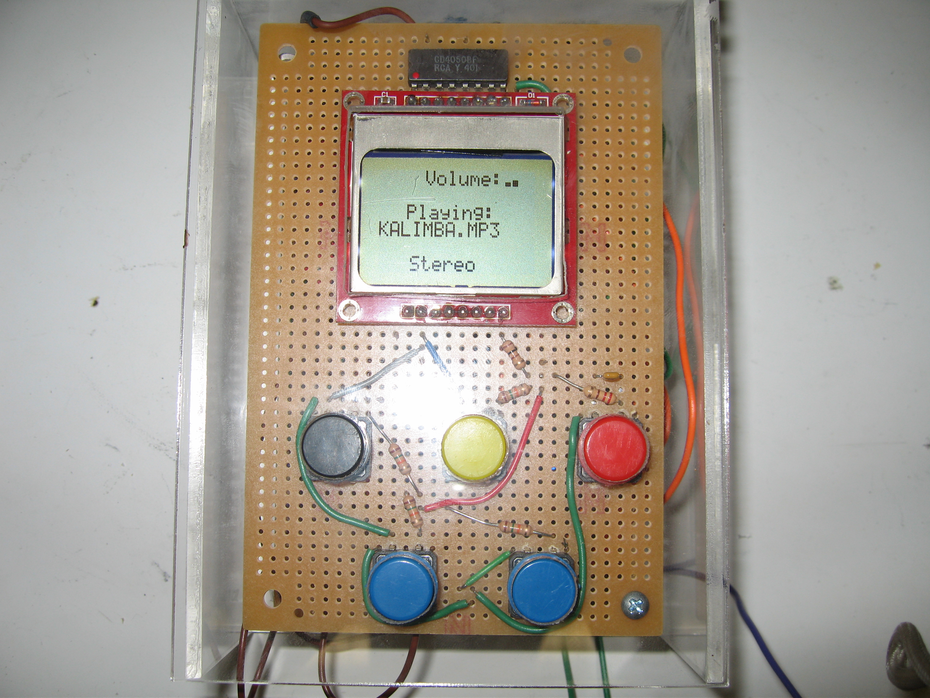
Final MP3 Player:

.JPG)
.JPG)
MP3 Player Code:
/*
* Thomas Carney's MP3 Player Code. My player
* has a audio mode, previous, stop, pause, and
* next button. We also have a volume control that
* draws bars based on the level. The audio mode can select between
* stereo, left stereo, right stereo, and double stereo
* Code contribution are from
* (c) 2010 david sirkin sirkin@stanford.edu
* and
* Matthew Seal (mattseal@stanford.edu)
*
*/
// Use 40*13 = 520 bytes of EEPROM
#include <nokia_5110_lcd.h>
#define MAX_FILE_COUNT 40
#define MAX_NAME_LENGTH 13
//LCD PINS
#define LCD_PWR 6
#define LCD_SCE 9
#define LCD_RESET 8
#define LCD_DC 7
#include <mp3.h>
#include <mp3conf.h>
// include the SD library:
#include <SD.h>
#include <EEPROM.h>
// set up variables using the SD utility library functions:
Sd2Card card;
SdVolume volume;
SdFile root;
Nokia_5110_lcd lcd(LCD_PWR, LCD_DC, LCD_SCE, LCD_RESET);
//#define DEBUG // Comment this line to remove debugging features
#define mp3_cs 5 // 'command chip select' to cs pin
#define sd_cs 10 // 'chip select' for SD card
#define dcs 14 // (Pin A0) 'data chip select' to bsync pin
#define rst 6 // 'reset' to decoder's reset pin
#define dreq 15 // (Pin A1) 'data request line' to dreq pin
#define read_buffer 256 // size of the microsd read buffer
//Define Button Pins
#define stopPin A2
#define nextPin A5
#define backSongPin A4
#define volumePin 6
#define switch1 4
#define switch2 2
#define audioSwitch A3
//MP3 variables
unsigned int mp3_vol=0; // output volume range is 0 to 254
volatile boolean paused=false;
bool playMusic=true;
bool triggerSongBack=false;
bool switch1Bool=false;
bool switch2Bool=false;
int currentSongI=0;
int audioMode=0; //0 is stereo. 1 is L,2 is R, 3 is Double Mono
int mainX=15;
int mainY=2;
int songNameX=0;
int songNameY=3;
int audioModeX=7;
int audioModeY=5;
char * currentSongName;
/* This function places the current value of the heap and stack pointers in the
* variables. You can call it from any place in your code and save the data for
* outputting or displaying later. This allows you to check at different parts of
* your program flow.
* The stack pointer starts at the top of RAM and grows downwards. The heap pointer
* starts just above the static variables etc. and grows upwards. SP should always
* be larger than HP or you'll be in big trouble! The smaller the gap, the more
* careful you need to be. Julian Gall 6-Feb-2009.
*/
uint8_t *heapptr, *stackptr;
uint16_t diff=0;
void check_mem() {
stackptr = (uint8_t *)malloc(4); // use stackptr temporarily
heapptr = stackptr; // save value of heap pointer
free(stackptr); // free up the memory again (sets stackptr to 0)
stackptr = (uint8_t *)(SP); // save value of stack pointer
}
/* Stack and heap memory collision detector from: http://forum.pololu.com/viewtopic.php?f=10&t=989&view=unread#p4218
* (found this link and good discussion from: http://www.arduino.cc/cgi-bin/yabb2/YaBB.pl?num=1213583720%3Bstart=all )
* The idea is that you need to subtract your current stack pointer (conveniently given by the address of a local variable)
* from a pointer to the top of the static variable memory (__bss_end). If malloc() is being used, the top of the heap
* (__brkval) needs to be used instead. In a simple test, this function seemed to do the job, showing memory gradually
* being used up until, with around 29 bytes free, the program started behaving erratically.
*/
extern int __bss_end;
extern void *__brkval;
int get_free_memory()
{
int free_memory;
if((int)__brkval == 0)
free_memory = ((int)&free_memory) - ((int)&__bss_end);
else
free_memory = ((int)&free_memory) - ((int)__brkval);
return free_memory;
}
/*
* Adopted from the ladyada.net tutorial on Ethernet protocol
* @http://www.ladyada.net/learn/arduino/ethfiles.html
*
* Lists all files from a directory:
* ListFiles(SdFile *dir, char *doubleBuf, int maxCount)
*
* dir is the directory to list
* doubleBuf is the buffer to store the results in -- this should be fileNames to start
* maxCount is the size of the buffer.
*
* returns the number of file names written into the doubleBuf array
*/
int ListFiles(SdFile *dir) {
int count = 0;
dir_t p;
dir->rewind();
while (dir->readDir(&p) > 0 && count < MAX_FILE_COUNT) {
// done if past last used entry
if (p.name[0] == DIR_NAME_FREE) break;
// skip deleted entry and entries for . and ..
if (p.name[0] == DIR_NAME_DELETED || p.name[0] == '.') continue;
/* Uncomment to allow subdirectories to be listed (with a '/' after the name) */
// only list subdirectories and files
//if (!DIR_IS_FILE_OR_SUBDIR(&p)) continue;
/* Uncomment to only allow files to be listed */
// only list files
if (!DIR_IS_FILE(&p)) continue;
// print file name into string
uint8_t pos = 0;
for (uint8_t i = 0; i < 11; i++) {
if (p.name[i] != ' ') {
EEPROM.write((count*MAX_NAME_LENGTH)+pos, p.name[i]);
pos++;
}
}
// append slash if file is a directory
if (DIR_IS_SUBDIR(&p)) {
EEPROM.write((count*MAX_NAME_LENGTH)+pos, '/');
pos++;
}
// add the end string character
EEPROM.write((count*MAX_NAME_LENGTH)+pos, '\0');
count++;
}
return count+1;
}
/*
* read in buffer 'bytes' of 'read_buffer' size from the file opened
* in the while loop below. This function assumes that file has already
* been opened and does NOT close the file. This means you need to do this
* outside of the function.
*/
void mp3_play (SdFile *file) {
clearSongName();
lcd.writeString(songNameX,songNameY,currentSongName,MODE_NORMAL);
unsigned char bytes[read_buffer]; // buffer to send to the decoder
unsigned int bytes_to_read; // number of bytes to read from sd card
// reset the file to be at the beginning of data
file->seekSet(0);
// Try to read 'read_buffer' length of bytes and send it to the decoder.
// If less than 'read_buffer' bytes are available, stop last send.
do {
//Stop Button.
if(digitalRead(stopPin)==LOW) {
delay(200);
playMusic=false;
}
//Switch Audio Mode
if(digitalRead(audioSwitch)==LOW) {
delay(200);
clearAudioName();
audioMode=(audioMode+1)%4;
setAudioMode();
}
//Go Back one song
if(digitalRead(backSongPin)==LOW) {
delay(200);
triggerSongBack=true;
break;
}
//Go to the next song
if(digitalRead(nextPin)==LOW) {
delay(200);
break;
}
if(!paused) {
bytes_to_read = file->read(bytes, read_buffer);
Mp3.play(bytes, bytes_to_read);
setAndDisplayVolume();
}
}
while (bytes_to_read == read_buffer &&playMusic);
}
//Sets and displays the audio mode
void setAudioMode() {
switch(audioMode) {
case 0:
switch1Bool=false;
switch2Bool=false;
lcd.writeString(audioModeX+10,audioModeY,"Stereo",MODE_NORMAL);
break;
case 1:
switch1Bool=false;
switch2Bool=true;
lcd.writeString(audioModeX,audioModeY,"Left Stereo",MODE_NORMAL);
break;
case 2:
switch1Bool=true;
switch2Bool=false;
lcd.writeString(audioModeX,audioModeY,"Right Stereo",MODE_NORMAL);
break;
case 3:
switch1Bool=true;
switch2Bool=true;
lcd.writeString(audioModeX-3,audioModeY,"Double Stereo",MODE_NORMAL);
break;
}
digitalWrite(switch1,switch1Bool);
digitalWrite(switch2,switch2Bool);
}
//Sets and displays the volume
void setAndDisplayVolume() {
int newVol=analogRead(volumePin)/4;
if(newVol!=mp3_vol) {
mp3_vol=newVol;
Mp3.volume(mp3_vol);
if(mp3_vol>100) drawRectangleVolume(1);
if(mp3_vol>150) drawRectangleVolume(2);
if(mp3_vol>200) drawRectangleVolume(3);
if(mp3_vol>240) drawRectangleVolume(4);
}
}
//Draws the volume rectangle
void drawRectangleVolume(int num) {
int darkArray[]={0,0,0,0};
for (int i=0;i<num;i++) {
darkArray[i]=1;
}
lcd.drawFilledRectangle(68,5,70,6,darkArray[0]);
lcd.drawFilledRectangle(72,4,74,6,darkArray[1]);
lcd.drawFilledRectangle(76,3,78,6,darkArray[2]);
lcd.drawFilledRectangle(80,2,82,6,darkArray[3]);
}
/*
* play back an mp3 or wav file (only!) in the root directory. first
* check that it's a file (and not a directory); next, check that it
* has a proper extension; finally, play only if it opens cleanly.
*/
void dir_play (SdFile *dir) {
int numFiles = ListFiles(dir);
for (int i = 0; i < numFiles; i++) {
char fn[MAX_NAME_LENGTH+2];
int fnln = MAX_NAME_LENGTH;
// get file name and name length
for (int j = 0; j < MAX_NAME_LENGTH; j++) {
fn[j] = EEPROM.read((i*MAX_NAME_LENGTH)+j);
// end of name
if (fn[j] == '\0') {
fnln = j;
j = MAX_NAME_LENGTH;
}
// directory => nullify entry name
else if (fn[j] == '/') {
fn[0] = '\0';
fnln = 0;
j = MAX_NAME_LENGTH;
}
}
if (fnln > 4) {
fn[fnln+1] = '\0';
fn[fnln] = fn[fnln-1];
fn[fnln-1] = fn[fnln-2];
fn[fnln-2] = fn[fnln-3];
fn[fnln-3] = '.';
fnln++;
}
SdFile dataFile;
// ensure we can open the file
if (dataFile.open(dir, fn, O_RDONLY) > 0) {
// ensure it's not a directory
if (!dataFile.isDir() || fn == 0) {
//get filenames in directory fn
//get length of the filename fnln
if ((fn[fnln-3] == 'M' && fn[fnln-2] == 'P' && fn[fnln-1] == '3') ||
(fn[fnln-3] == 'W' && fn[fnln-2] == 'A' && fn[fnln-1] == 'V')) {
//buffer data for playing
//We have not been asked to go back a song so play the next song
if(!triggerSongBack) {
currentSongName=fn;
mp3_play(&dataFile);
}
else
{
//To go back a song we must substract i by 3.Break out of the inital
//play loop say i=1. When we reach this point i=2 becuase we went through
//the loop again. When we leave this point and go back to the beginning of the
//loop i will be 3; however the "previous song" we want is at i=0. Hence i=i-3;
triggerSongBack=false;
i=i-3;
}
}
}
}
}
}
/*
* initialize the processor speed, setup the fatfs sd card (or, mms)
* filesystem, setup mp3 playback and register the pins used (device
* specific configuration)
*/
void setup() {
lcd.init();
lcd.clear();
//Serial.begin(9600); // initialize the serial terminal
pinMode(10, OUTPUT); // change this to 53 on a mega
digitalWrite(10, HIGH);
//Audio Switching Pins
pinMode(switch1,OUTPUT);
pinMode(switch2,OUTPUT);
//Button Pins
pinMode(audioSwitch,INPUT);
pinMode(stopPin,INPUT);
pinMode(nextPin,INPUT);
pinMode(backSongPin,INPUT);
pinMode(volumePin,INPUT);
//Pause Button Interrupt
attachInterrupt(1,pauseSong,FALLING);
// see if the card is present and can be initialized:
if (!SD.begin(sd_cs)) {
lcd.writeString(0,0,"Card Not loaded",MODE_NORMAL);
// don't do anything more:
return;
}
// we'll use the initialization code from the utility libraries
// since we're just testing if the card is working!
if (!card.init(SPI_HALF_SPEED, sd_cs)) {
lcd.writeString(0,0,"Card is not working",MODE_NORMAL);
return;
}
// Now we will try to open the 'volume'/'partition' - it should be FAT16 or FAT32
if (!volume.init(card)) {
lcd.writeString(0,0,"Could not find FAT16/FAT32 partition.\nMake sure you've formatted the card",MODE_NORMAL);
return;
}
if (!root.openRoot(&volume)) {
lcd.writeString(0,0,"Failed to open root",MODE_NORMAL);
// don't do anything more:
return;
}
digitalWrite(switch1,switch1Bool);
digitalWrite(switch2,switch2Bool);
lcd.writeString(audioModeX+10,audioModeY,"Stereo",MODE_NORMAL);
Mp3.begin(mp3_cs,dcs,rst,dreq); // decoder cs, dcs, rst, dreq pin
Mp3.volume(mp3_vol); // default volume level is silent
// List all files to in the root directory and play each
// one at a time. Maximum of MAX_FILE_COUNT files will be read
lcd.writeString(25,0,"Volume: ",MODE_NORMAL);
lcd.writeString(mainX,mainY,"Playing:",MODE_NORMAL);
}
void clearMainMessage() {
lcd.drawFilledRectangle(0,16,83,23,0);
}
void clearSongName() {
lcd.drawFilledRectangle(0,23,83,30,0);
}
void clearAudioName() {
lcd.drawFilledRectangle(0,35,83,47,0);
}
//This is the function to pause a song
void pauseSong() {
clearMainMessage();
delay(1000);
if(paused) {
lcd.writeString(mainX,mainY,"Playing:",MODE_NORMAL);
}
else{
lcd.writeString(mainX,mainY,"Paused:",MODE_NORMAL);
}
paused=!(paused);
}
//The main loop
void loop() {
delay(100);
dir_play(&root);
if(!playMusic) {
clearMainMessage();
clearSongName();
lcd.writeString(mainX,mainY,"Stopped",MODE_NORMAL);
}
while(!playMusic) {
if(digitalRead(stopPin)==LOW) {
playMusic=true;
lcd.writeString(mainX,mainY,"Playing:",MODE_NORMAL);
}
}
}