Lab 2: Frankenlight
Introduction: We learned how to successfully configure our Arduino to blink a led on and off. We were able to create a blinking light with different speeds, a fading light which increased in brightness by linearly changing PWM, and a fading light which varied brightness linearly to our eyes by changing PWM geometrically. We created a frankenlight from a timer.
Part A: 1: We created the blink program following the example.
a. What lines of code do you need to change to change the rate of blinking?
To change the rate of blinking we modify the delay function in both lines. For example, we can change the code from on, delay 1 second, off, delay one second creating a blink rate of one second, to every half second by making the delay(500) instead of delay(1000).
b. What circuit element do you need to add to protect the board and LED?
To protect the board and LED we must add a resistor to regulate current. In keeping with the previous lab, we use 220 Ω.
2: We built the two circuits to create our button circuit. In one configuration we had a pullup resistor and in the other we had a pulldown resistor. Hence in the pullup resistor configuration the button pin was high and hence the led pin was high. We rearranged the circuit by configuring the button pin to a pulldown resistor and hence when the button pin was low, the led pin was low
a. Which lines do you need to modify to correspond with your button and LED pins?
We simply needed to change the button pin number to 9 for our circuit to work where pushing the button turns the led off with the pullup
b. Modify the code or the circuit so that the LED lights only while the button is depressed. Include your code in your lab write-up.
If we use a pullup resistor than we must change the if statement logic. If the button is open, the button pin is high and the led pin needs to be low.
// set pin numbers:
const int buttonPin = 2; // the number of the pushbutton pin
const int ledPin = 9; // the number of the LED pin
// variables will change:
int buttonState = 0; // variable for reading the pushbutton status
void setup() {
// initialize the LED pin as an output:
pinMode(ledPin, OUTPUT);
// initialize the pushbutton pin as an input:
pinMode(buttonPin, INPUT);
}
void loop(){
// read the state of the pushbutton value:
buttonState = digitalRead(buttonPin);
// check if the pushbutton is pressed.
// if it is, the buttonState is HIGH:
if (buttonState == LOW){
// turn LED on:
digitalWrite(ledPin, HIGH);
}
else {
// turn LED off:
digitalWrite(ledPin, LOW);
}
}
3. We created the fading LED light by combining the button code and the fading light code.
a) Which lines do you need to modify to correspond with your button and LED pins?
We replaced the “digitalWrite(ledPin, HIGH) ” line in the button code with the follow to create the fading LED
// fade in from min to max in increments of 5 points:
for(int fadeValue = 0 ; fadeValue <= 255; fadeValue +=5) {
// sets the value (range from 0 to 255):
analogWrite(ledPin, fadeValue);
// wait for 30 milliseconds to see the dimming effect
delay(30);
}
// fade out from max to min in increments of 5 points:
for(int fadeValue = 255 ; fadeValue >= 0; fadeValue -=5) {
// sets the value (range from 0 to 255):
analogWrite(ledPin, fadeValue);
// wait for 30 milliseconds to see the dimming effect
delay(30);
}
b) How would you change the rate of fading?
We changed the rate of fading by increasing or decreasing the fadeValue parameter in the for loop.
c - extra) Since the human eye doesn't see increases in brightness linearly how could you change the code to make the light appear to fade linearly?
We inserted the following code in place of the code in part b. Instead of increasing the PWM linearly we increased it geometrically. The light appeared to our eyes to fade linearly. The 1.1 is the rate of fading. We can increase or decrease it to adjust the speed of fading.
double fadeValue=1;
double fadeValueMax=255;
while(fadeValue<fadeValueMax) {
analogWrite(ledPin,fadeValue);
fadeValue=fadeValue*1.1;
delay(30);
}
while(fadeValue>1) {
analogWrite(ledPin,fadeValue);
fadeValue=fadeValue/1.1;
delay(30);
}
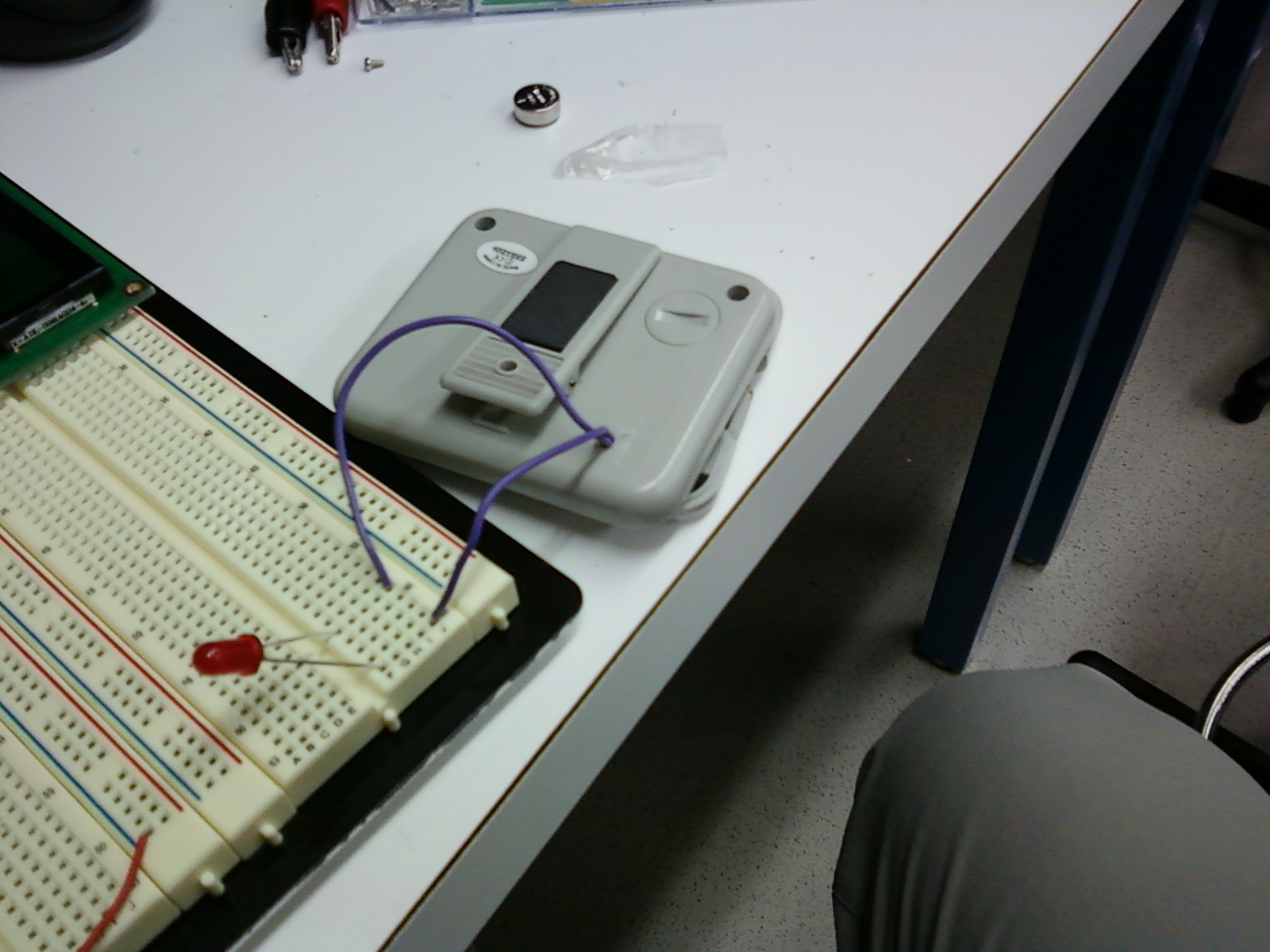
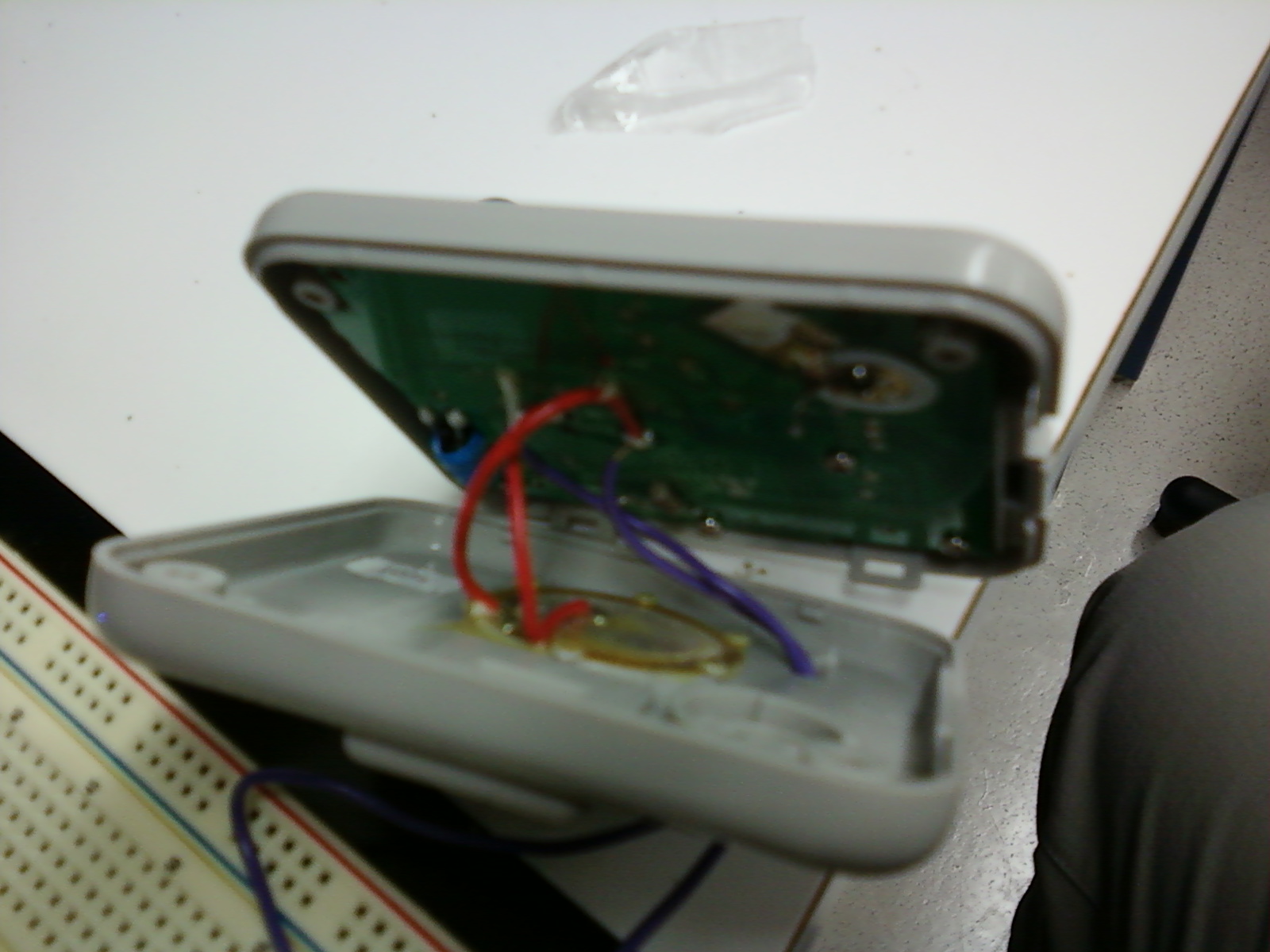
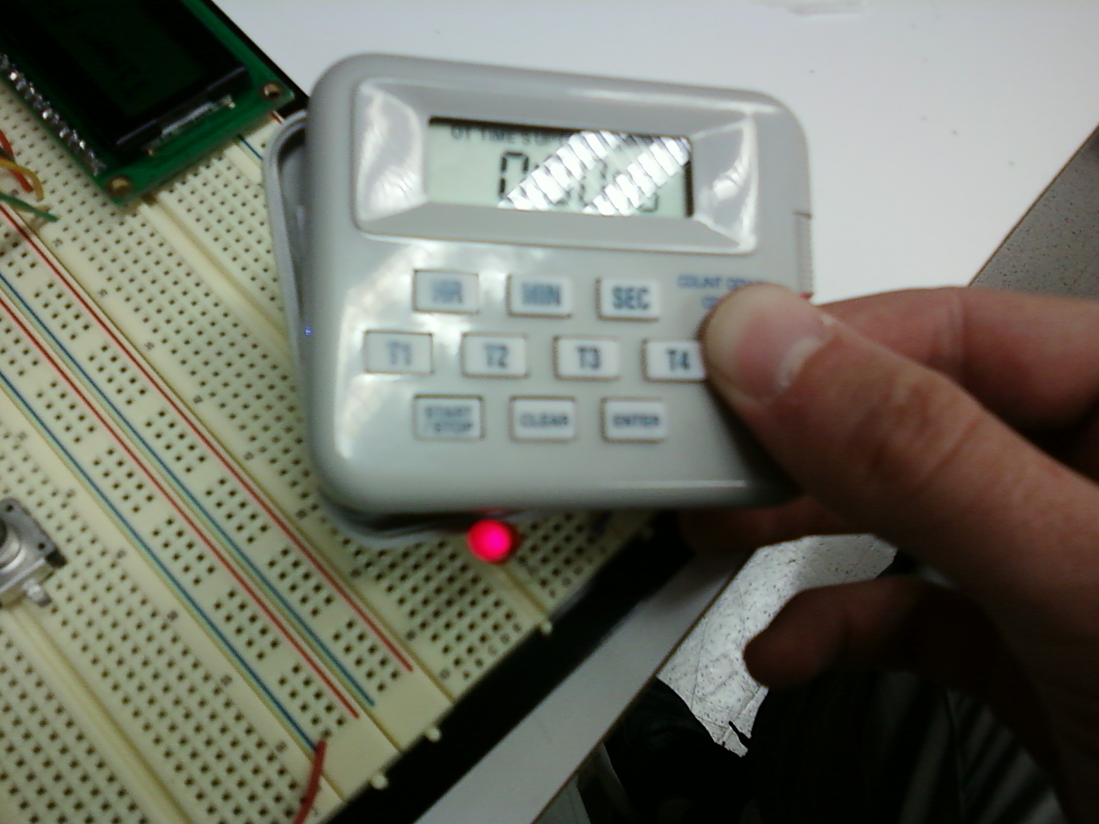
Part B: 1: We chose to take apart a digital countdown timer and wire the LED so that it blinks when the speaker plays a buzzing noise. We were able to successfully create our Frankenlight using the bright LED but it was too dim. If we had more time we would have liked to use a transistor and an external circuit to allow the LED to draw more current. Instead of using the bright LED, we took pictures of our device using a red LED because it was brighter and required less current.
a. What is the minimum resistor size that should be used with these LEDs (hint: think about your voltage supply and what the diode voltage drop means)?
We have a voltage supply of 5V, and assuming that the diodes have a forward drop of 3.4 V, then 1.6V will be dropped across the resistor. To ensure 20 mA we must have 1.6V/20 mA=80 Ω resistor
2: Schematic of Device:
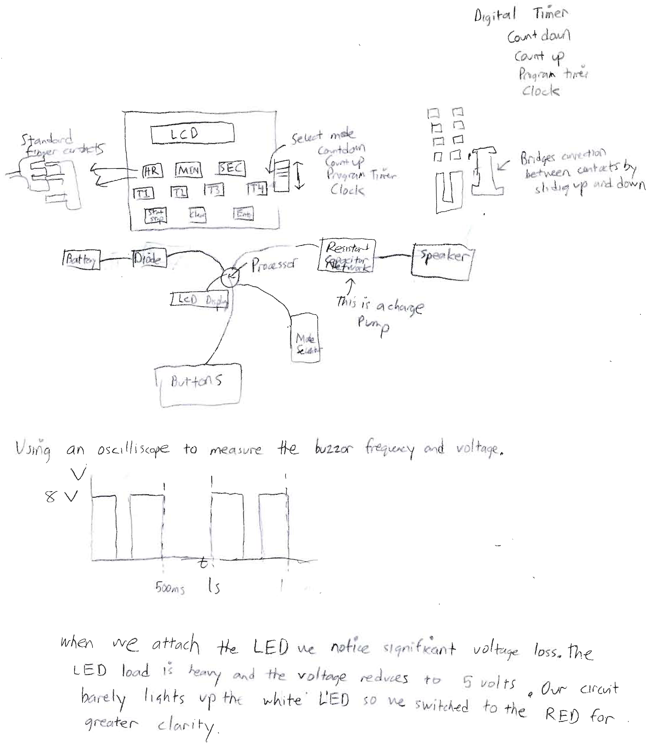
a. Is there computation in your device? Where is it? What do you think is happening inside the "computer"?
The digital timer receives input from the buttons on the mode it should be in as well as the starting conditions. The timer than uses a clock signal to countdown the time, displays the remaining time, and signals a speaker to indicate its completion.
b. Are there sensors on your device? How do they work? How is the sensed information conveyed to other portions of the device?
The only sensors are the button on the front of the device. They work by touching conductive rubber in between fingered electrical contacts. The slide switch for selecting the mode works by connecting individual contacts corresponding to individual modes with a main contact.
c. How is the device powered? Is there any transformation or regulation of the power? How is that done? What voltages are used throughout the system?
The device is powered by a 1.5 V Li-ion battery. The voltage is stepped up to 8V at the expense of the current to power the speaker. A charge pump is used to achieve this.
d. Is information stored in your device? Where? How?
Information is stored in the device in some sort of memory inside the processor. We notice no external chips outside the microprocessor corresponding to memory.
Pictures of Frankenlight
 |
 |
 |
|