Barebones MP3 Player
Overview
We'll get our MP3 player playing songs! The design component for this lab is your final project (phew).
In The Report
Include your responses and uploads to the green questions, and show a video of your MP3 player playing a song! Your responses, code, and video are due one week after your lab session.
Kit Parts
Don't forget to collect the new parts for your kits by the printer!
Grade Lab 5 Together
Find a partner! Look at each other's lab reports and discuss answers to lab 5 as well as the other parts of the lab report (schematic, videos, etc). Then assign each other a grade according to the scale discussed in class: Check++ (10), Check+ (9), Check (8), Check-- (7). Ask an instructor if you have questions about the grading scale. After you're finished, email your scores to ee47-sum1415-staff@lists.stanford.edu .
Part A. Audio Jack
We are using a 3.5mm audio jack in this lab. This type of jack is called 'TRS' for Tip, Ring and Sleeve.
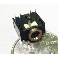
When you return, look carefully at the datasheet for the audio jack; in particular, the "schematic" view on the far right. The "schematic" detail is a graphic representation of the jack. It shows pins 1, 2 and 3, which represent ground, tip, and ring, respectively. The bottom of the jack is labelled with the pinout (pins 1, 2, and 3). Pin 3 would connect to what looks like a ring on your audio plug and pin 2 would connect to the tip.
In order to place the jack on your breadboard, you'll have to cut off the small black posts on the bottom of the jack with an exacto knife and twist pin 1 (GND) by 90 degrees (see pic below). Place the jack on your breadboard and mark the pins with different color wire representing pin 1 (GND), pin 2 (TIP), and pin 3 (RING).

Use headphones and a function generator to output a 80 mVpp (millivolts, peak-to-peak), 440 Hz, sine wave between TIP and GND, then RING and GND to check that your audio jack is connected to the breadboard. When outputting to TIP, the left ear should hear a tone, and when outputting to RING, the right ear should hear a tone.
NOTE: It can be difficult to get a good connection with the jack, even after making the modifications described above. If you're still having trouble, consider soldering jumper wire extensions onto the pins.
Part B. Connect And Test Your Decoder
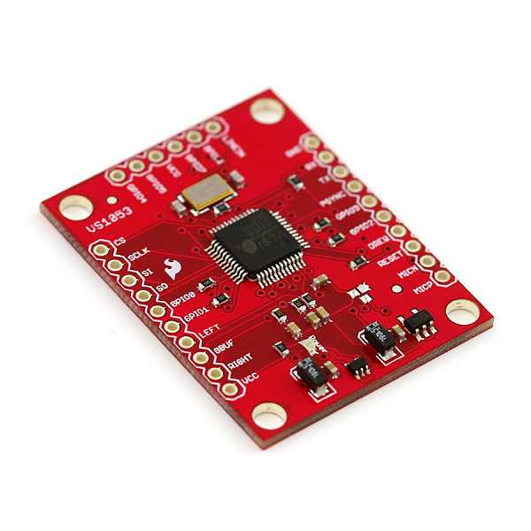
Your second task is to wire up and test your mp3 decoder. We're using a breakout board for the VS1053, which is based on VLSI's VS1053 decoder chip. You can check out the datasheet here.
Note: Solder straight header pins to the two long sides of the decoder. Don't solder the top row, otherwise you won't be able to fit the decoder in your breadboard!
We're including links to 2 Mp3 libraries. Either should work fine, and they're both quite similar to each other, but just in case one doesn't work well, try the other...
1. Install this Mp3 library (or the VS1053 library) in your Arduino IDE "libraries" folder (both for your personal and lab computer).
2. Wire up the decoder and your audio jack to your breadboard. It's fine if your microSD card is already connected to the Arduino Micro. Just leave it connected and add the new components into the circuit. Remember how in Lab 5 the Graphical LCD and microSD card shared the SPI bus? Well, the audio decoder is about to join them! Connect your new parts like this:
| Decoder |
Connect
|
Connection |
| CS |
--> |
4050 Pin 15 |
| SCLK |
--> |
4050 Pin 2 |
| SI |
--> |
4050 Pin 4 |
| SO |
-->
|
Arduino MISO (MI)
|
| VCC |
--> |
3.3V |
| GND |
--> |
GND |
| BSYNC (DCS) |
--> |
4050 Pin 12 |
| DREQ |
--> |
A2 |
| RST |
--> |
4050 Pin 10 |
Retaining your previous 4050 level shifter wiring, add the following if necessary:
| 4050 |
|
Arduino |
| Pin 3 |
--> |
Arduino SCK |
Pin 5
|
-->
|
Arduino MOSI (MO) |
| Pin 7 |
--> |
Arduino SS
|
| Pin 9 |
--> |
Arduino Reset (RS)
|
| Pin 14 |
--> |
A0 |
| Pin 11 |
--> |
A1 |
| Decoder |
Connect
|
Audio Jack
|
| LEFT |
--> |
Pin 2 (TIP)
|
| GBUF |
--> |
Pin 1 (GND on jack NOT Arduino Micro GND) |
| RIGHT |
--> |
Pin 3 (RING) |
3. Load the test program in Examples->Mp3->SineTest.
If your MP3 encoder and jack are connected right, you should hear tones that lasts for 1 second, then silence for 1 second, in a repeating pattern.
Describe the tone pattern you hear (i.e., high or low, how long, etc.).
If you're not hearing anything and you're sure your wiring is correct, try increasing the default volume (described next). Different headphones have different signal-strength sensitivities, so audio that's comfortable on one set may be too quiet to hear on another.
Now, uncomment the #define DEBUG line in the SineTest code, reflash the Arduino Micro, reboot, and check the serial monitor. (If you do this, it will take 15-20 seconds for the SineTest tones to start.) The program should report the following:
Wrote 820 to address 0
Wrote 0 to address 3
Wrote 8181 to address B
Read SCI_MODE: 820
Read CLOCK_F: 0
Read SCI_VOL: 8181
These are the decoder's operating settings, and the register addresses to write them into. The first setting is the mode. A value of 0x0800 puts the decoder into normal (or so-called 'new') mode. This is the (default) value to use most of the time. We're using 0x0820 here to allow us to run tests (like the sine test).
The second setting is the decoder's clock multiplier. For the SineTest, we don't use any multiplier.
The third setting is the volume. This works inverse to what you would think: 0 is full volume, while 0xFEFE is nearly silent. The left (most-significant) byte (0x81) is the value for the left channel, and the right (least-significant) byte (also 0x81) is for the right channel. The original default vol is 0x8181. The channels don't have to be the same.
Edit the following line in the SineTest code to change the DEFAULT_VOL to 0x6565 (or something similar) to make it louder:
void setup() {
...
write_sci(SCI_VOL, DEFAULT_VOL);
...
}
If that worked, you now know how to change other settings (which are listed on page 37 of the datasheet), such as left-right channel phase (for an 'expanded stereo' sound, described in section 8.7.1), bass enhancement (described in section 8.7.3), and even playback speed (described in section 9.5). Neat!
Part C. Play Some Music!
Once the sine test is working, your third task is to jam! Er, to play a file from the microSD card. Think of it like this: in Lab 5, we read a block of bytes from a file, then streamed them to the serial terminal or the Graphical LCD. The read() function automatically advanced the read/write pointer for us, so we could loop over these 2 steps until there were no more bytes to be read. Well, we're doing the same thing now, only we're streaming a block of bytes (representing audio) to the decoder, instead of a block of bytes (representing a graphic) to the LCD. That's it!
Please note that you may need to change your wiring Graphical LCD as the 4050 has only 6 pairs of function terminals. The revised connections are shown below:
| Graphical LCD |
Connect
|
Connection |
| GND |
--> |
Arduino GND (same)
|
| Vcc |
--> |
3.3V (same)
|
| CLK |
--> |
4050 Pin 2
|
| DIN |
-->
|
4050 Pin 4
|
| D/C |
--> |
1:2 Voltage Divider to
Arduino A4
|
| CS |
--> |
1:2 Voltage Divider to
Arduino A3
|
| RST |
--> |
4050 Pin 10
|
| LED |
--> |
3.3V (same)
|
Voltage Divider:
A voltage dividing circuit is shown below. For our purposes, Vin = 5V and we want Vout = 3.3V, so we should choose R1/R2 = 1/2 (i.e. R1 = 10 kOhms and R2 = 20 kOhms).


Now load the MP3 player program in Examples->Mp3->Song.
If everything is wired correctly to the MP3 decoder above and your SD card is working, this code should play the songs on your SD card and display their titles on the LCD. (If you don't have an LCD connected, it should still work.)
We've pre-loaded several songs onto your microSD card. If all goes well, you should be able to share audio bliss with your labmates, friends and family. Congratulations!
Tell a member of the teaching team what your song is (or better yet, play it for us).
Now look at the example code a bit: specifically the dir_play() and setup() functions.
Does this code play all the songs in all the directories of the SD card? If not, which songs does it play? How does it keep from playing the text file?
Then, look at the Utilities module of the example code. In particular, focus on the sd_card_setup() and sd_dir_setup() functions. Note how they interact with card data.
Here are some useful file management functions that can be used on a SdFile object. These are used in the example code.
Change the Song (or Simple_MP3_V2) program to save the current volume setting in your EEPROM, then fetch and set that value during initialization. Note that the first max_num_songs * max_name_len (in this case, 520) bytes of the EEPROM are used to store file names, so don't overwrite those.
To add audio files to your microSD card, you can use the Lab's USB card reader, which usually resides in box with the camera by the TA table. The card should auto-mount on your computer, so you can copy over files and check the root directory to make sure the new files are, in fact, there. When you're done, just re-insert the card into your adapter, the adapter into your player, and return the reader to its home in the box.
But wait, there's more...
Part D. Pause to Learn About Interrupts
What if you want to play or stop playing a song on command?
The Arduino Micro has 4 pins with external interrupts built in, on pins 0 (RX), 1 (TX), 2, and 3 (which correspond with interrupt 2, 3, 1, and 0, respectively). You can use them by using the attachInterrupt() function, which is part of the extended Arduino language. The Arduino Micro uses the same definitions as the Arduino Leonardo.
Try the sample code from the attachInterrupt() reference page with a button circuit that is tied high with a 10K resistor and that gets pulled to ground when the button is depressed.
In general (as in the sample code), when you set or change a variable within an interrupt service routine (ISR), you should declare that variable as volatile, to tell the compiler to load its value from RAM instead of storing it in a register to optimize.
Draw us a quick sketch of what your circuit looks like.
What happens when you press the button? What happens when you press the button 15 times in a row?
To debounce the button in software, you can create a "bouncer" object that waits a bit before reading the button. You can find the Arduino playground page here.
What are the pros and cons of using this method?
To couple interrupts and debouncing, as demonstrated in class, modify code at the Arduino Forum on Debouncing & Interrupts. Consider lowering the 200ms debounce time if you want to press buttons in quick succession, although we don't recommend going below 20ms.
Now, take what you learned to make an interrupt driven pause function for your Barebones MP3 player!
Note that you may have to use the mp3.clear_buffer()function.
Part E. Input Knob (Optional)
What if you want to change the volume? You can modify the following code:
/*
* Encoder_test
* Based on code by Paul Badger
* ----------------------------
* WGJ 6MAY10: Updated pins, serial speed for Arduino Micro
*
* Read a rotary encoder with interrupts
* Encoder hooked up with common to GROUND,
* encoder0PinA to pin 6, encoder0PinB to pin 7
* it doesn't matter which encoder pin you use for A or B
*
* Uses Arduino pullups on A & B channel outputs
* turning on the pullups saves having to hook up resistors
* to the A & B channel outputs
*/
#define encoder0PinA 2
#define encoder0PinB 3
volatile unsigned int encoder0Pos = 0;
void setup() {
Serial.begin (115200);
pinMode(encoder0PinA, INPUT);
digitalWrite(encoder0PinA, HIGH); // turn on pullup resistor
pinMode(encoder0PinB, INPUT);
digitalWrite(encoder0PinB, HIGH); // turn on pullup resistor
attachInterrupt(0, doEncoder, CHANGE); // encoder pin on interrupt 0 - pin 2
Serial.println("start");
}
void loop() {
/* Do some stuff here - the joy of interrupts is that they
* take care of themselves
*/
}
void doEncoder() {
/* If pinA and pinB are both high or both low, it is spinning
* forward. If they're different, it's going backward.
*/
if (digitalRead(encoder0PinA) == digitalRead(encoder0PinB)) {
encoder0Pos++;
} else {
encoder0Pos--;
}
Serial.println (encoder0Pos, DEC);
}
Part F. Song List (Optional)
If you want some more functionality, here is an additional part you could add to your mp3 player. In the Song.pde example script the code lists all files in the root directory and plays any that are songs. However, it plays them in a specific order and is limited to loading ~40 songs. To help alleviate this problem, create a song list that contains all songs you want to play in a certain order and load the files to play in the correct sequence. From here you could do a lot to allow user input on song lists!
Comments (0)
You don't have permission to comment on this page.