Make your own LED Light
Overview
We'll start our tutorial with several simple light circuits. In the first one shown below, the LED is permanently on. In the second one, the LED only lights up when a button is pressed and a circuit is completed. In the third one, we'll replace the manual switch with an Arduino pin (set to output mode), so we can control the LED from our program. Here are three simple circuits to build on your breadboard:
Assignment
Work your way through Parts A, B and C in lab. Questions 2-4 of Part C may be completed outside of lab, but we encourage you to work on them here, so we can help along the way.
In The Report
Include your responses to all of the green questions in your lab report. Show your calculations. Please follow the Lab Report Guidelines. The last three questions (in Part C, Build Your LED Light) should be uploaded to a wiki page so that others can see your cool ideas. As stated in the guidelines, all deliverables are due one week after your lab session.
Part A. Basic Circuitry
1. Basic LED circuit on breadboard
Power your breadboard by hooking up the power and ground cables from the bench power supply (set to +5V) to your breadboard. Use jumper wire to connect these to the red (power) and blue (ground) rails on your breadboard.

Build the following circuit on your breadboard. Use a 220 Ohm resistor, and a yellow, green or red LED to start out with.
Because LEDs are diodes, they have directionality (resistors and wires don't). The longer arm of the LED should be on the end of the circuit with higher potential. (Remember, the long arm reaches for power!)

Check your circuit before connecting it to power. While getting the circuit right is important to having your LED light up, the more crucial thing to check is to make sure that power is not shorted to ground. Let's repeat that: DON'T SHORT POWER TO GROUND. Shorting power to ground makes really large amounts of current to flow through your circuits, and is liable to damage your components and the power supply.
If your circuit is good, the LED should light up and stay on. If it doesn't you probably need to switch the orientation of the LED.
2. Controlling the brightness of LEDs
Now add a potentiometer (or a pot) in series with the resistor to control the brightness of your LED. Do NOT remove the resistor entirely, or it is very possible you will destroy your LED. The typical max continuous DC forward current rating for a red LED is 20mA. Here are the datasheets for your red, yellow and green LEDs.
a. What resistance do you need to limit current to 20 mA?
b. Is 220 ohms a maximum or minimum resistance?
c. What is the resistance range of the potentiometer?

3. Basic LED circuit with switch on breadboard
Next, we'll insert a switch into the circuit. The momentary switches in your kit are "normal open," meaning that the circuit is interrupted in the idle state, when the switch is not pressed. Pressing the switch closes the circuit until you let go again.


a. Does it matter what order the components of your circuit are arranged between power and ground? Why or why not?
4. Battery-powered LED with switch on breadboard
Now, let's make things a little more portable. Disconnect the breadboard from the power supply. Use the battery clip and a 9V battery to power your LED circuit. You'll need to replace your 220 Ohm resistor for the higher voltage.
a. What is the minimum resistance required for use with the battery?
Part B. Starting with the Arduino!
If you'd like to use your own laptop computer for programming the Arduino, now is a good time to download and install the software on your machine. On the lab machines, the Arduino software is at:
Start->All Programs->Sanguino->Sanguino
1. Blinking LEDs with the Arduino Teensy
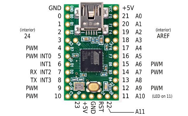
Connect the Arduino to your computer using the USB cable. The Arduino Teensy comes preloaded with the Blink program on it, so its orange LED should start blinking as soon as the USB cable starts powering the board. This LED is hardwired to pin 11 of the Arduino Teensy. (This is different than traditional Arduinos, which have an LED hardwired to pin 13! You'll need to change the Arduino example code accordingly.)
The Blink program can be found in the Arduino IDE's example code folder under File->Examples->Digital->Blink. Check it out!
a. What line of code do you need to change to light the Teensy LED?
b. What lines of code do you need to change to change the rate of blinking?
To compile and upload your code:
1) First make sure that the Teensy Loader program is running (The "teensy" link on the desktop).
2) In the Arduino program, select the board we are using (Tools->Board->Teensy 2.0 (USB serial),
3) To compile and upload your code, click on the circular "play" button on the upper far left of the Arduino development window.
4) When the code is uploaded, hit the black reset button on your Teensy to reboot it and start running your new code.
Now modify the program so that you can blink an external LED on pin 9 (labeled C6 on the Teensy).

2. Toggle LEDs on and off using the Arduino Teensy
With your LED still connected on digital pin 9, hook up a button circuit on digital pin 2 (labeled B2 on the Teensy), so that the pushbutton attached from pin 2 to ground, and so that there is a 10K resistor attached to pin 2 to Vcc (5 or 9V, depending on whether you are using the power supply or the battery).

Use the Button program (File->Examples->Digital->Button) to make your Teensy into a light switch.
a. Which lines do you need to modify to correspond with your button and LED pins?
b. Modify the code so that the LED lights only while the button is depressed. Include your code in your lab write-up.
3. Fading LEDs on and off using the Arduino Teensy
What about those "breathing" LEDs on Mac Powerbooks? The fading from bright to dim and back is done using pulse-width modulation (PWM). In essence, the LED is toggled on and off rapidly, say 1000 times a second, faster than your eye can follow. The percentage of time the LED is on (the duty) controls the perceived brightness. To control an LED using PWM, you'll have to connect it to one of the pins that support PWM output - 9, 10 or 11 on the Arduino. (C6, C7, and D6 on the Teensy, respectively)
Use the Fading program (File->Examples->Analog->Fading) to make your LED fade in and out.
a) Which lines do you need to modify to correspond with your button and LED pins?
b) How would you change the rate of fading?
Part C. Your LED light
1. Super bright LEDs
We have included some nifty superbright LEDs in your kit. They are clear and have two leads. The link to their datasheet is here. They have a 3.4V forward drop, and a max current rating of 20mA.
a. What is the minimum resistor size that should be used with these LEDs?
Try prototyping a circuit with the superbrights. (Be careful! They are bright enough that it hurts your eyes to look at them!)
2. Sketch 20 ideas for a specific application for LED lights
Yes, we want a photo of all 20 ideas on your lab 2 wiki page.
3. Build 10 paper prototypes of your favorite LED light ideas
Yes, we want a photo of all 10 prototypes on your lab 2 wiki page.
4. Build your light!
We have perfboards in the lab, which provide a handy way to connect your parts. (These are what we used during the soldering demo.) You may want to make your light using passive components (such as switches, resistors, potentiometers) rather than your microcontroller (also known as a μC), unless you think of a nice way to incorporate the μC into your design without soldering it inside of a light. (You'll need it back for future labs and projects!) If your design does require a μC, perhaps you can run a lead from your breadboard to the main light, although you'll lose portability that way. Clever use of components is encouraged!
Give yourself enough time to build your design. Consider re-visiting the lab during another session, so you can access components, tools, soldering irons.
The best design will win a free pass to Maker Faire, May 22nd and 23rd!
Typical max Continuous DC Forward Current ratings for a red LED are 30mA.
What resistance value does this correspond with?
Is that a maximum or minimum resistance?
Comments (0)
You don't have permission to comment on this page.